PNP vs NPN vs Relay Flow Switch Outputs: How to Wire NO/NC to a PLC
Author: Leo
SEO Title: PNP vs NPN vs Relay Flow Switch Outputs Explained
Meta Description: Learn how to choose PNP, NPN or relay flow switch outputs and wire NO/NC signals to a PLC. Includes 24 VDC wiring examples and NK210 specifications.
Suggested URL Slug: /pnp-npn-relay-flow-switch-plc-wiring/
Direct Answer
Choosing a PNP, NPN or relay flow switch output depends on the PLC input type, supply voltage, load requirements and whether electrical isolation is needed. For a typical 24 VDC PLC input, a PNP output supplies positive voltage to the input, while an NPN output switches the signal toward 0 V. A relay output uses contacts to open or close a circuit within its rated electrical limits.
NO (Normally Open) and NC (Normally Closed) describe the output’s normal state, not whether the sensor is PNP, NPN or relay. For reliable operation, verify the manufacturer’s definition of the normal state, the PLC input wiring and the required response to power loss or a broken wire before commissioning a flow alarm or pump-protection interlock.
Key Takeaways
- PNP vs NPN: Select the output according to the PLC input module’s sourcing or sinking configuration.
- Relay output: Useful when dry contacts, circuit isolation or compatible AC/DC switching are required, provided the contact ratings are suitable.
- NO vs NC: These describe normal output logic and must be checked separately from output type.
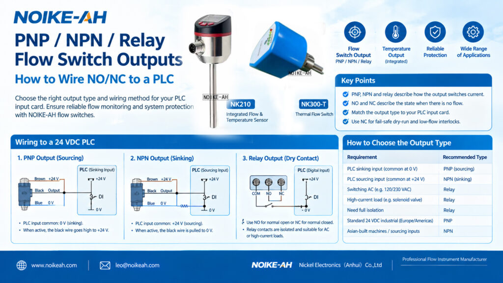
- Wire colors: A common 3-wire DC sensor arrangement uses brown for positive supply, blue for 0 V and black for the switched output. Always confirm the specific wiring diagram.
- Equipment protection: Test the complete sensor–PLC circuit, including power loss and broken-wire behavior, before using it for a protective interlock.
1. What Are PNP, NPN and Relay Flow Switch Outputs?
A flow switch detects whether a process flow condition meets a configured threshold and provides an electrical output to a PLC, controller or alarm circuit.
PNP, NPN and relay describe three common output arrangements.
| Feature | PNP Output | NPN Output | Relay Output |
|---|---|---|---|
| Output technology | Transistor | Transistor | Mechanical contact |
| Typical ON behavior | Supplies positive voltage to the load | Pulls the signal toward 0 V | Opens or closes contacts |
| Polarity | DC polarity must be observed | DC polarity must be observed | Contacts are generally non-polarized within their ratings |
| Switching behavior | Electronic, typically fast | Electronic, typically fast | Mechanical, typically slower |
| Mechanical contact wear | No | No | Yes |
| Common applications | Compatible 24 VDC PLC inputs | Compatible 24 VDC PLC inputs | Isolated switching and compatible AC/DC circuits |
The actual output voltage, current rating, leakage current, switching frequency and protection features vary by model. Check the manufacturer’s datasheet before connecting the device.
2. What Is the Difference Between PNP and NPN?
The key difference is how the transistor output controls current through the connected load.
PNP Flow Switch Output
A PNP output is commonly described as a sourcing output. When activated, it supplies positive voltage to the load or PLC input.
For a typical three-wire 24 VDC sensor:
- Brown: +24 VDC supply.
- Blue: 0 VDC supply.
- Black: switched output to the PLC digital input.
- PLC input common: typically connected to 0 V for a compatible sinking input arrangement.
When the output activates, the black wire rises toward the positive supply voltage and the PLC input detects the ON state.
NPN Flow Switch Output
An NPN output is commonly described as a sinking output. When activated, it pulls the signal toward 0 V.
For a typical three-wire 24 VDC sensor:
- Brown: +24 VDC supply.
- Blue: 0 VDC supply.
- Black: switched output to the PLC digital input.
- PLC input common: typically connected to +24 V for a compatible sourcing input arrangement.
When the output activates, the black wire is pulled toward 0 V, allowing current to flow through the PLC input circuit.
Important: The terms sourcing and sinking are used from the perspective of the current path. Check the PLC manufacturer’s documentation because input-module terminology and wiring conventions can vary.
3. What Do NO and NC Mean on a Flow Switch?
NO and NC describe the output’s normal, unactuated state. For a flow switch, that state may correspond to no flow, but the manufacturer’s definition must be verified.
Under the common convention in which no flow is the normal state and flow detection actuates the switch:
| Condition | NO Contact | NC Contact |
|---|---|---|
| Normal no-flow state | Open | Closed |
| Flow condition actuates switch | Closed | Open |
For transistor outputs, NO/NC may refer to configurable switching logic rather than a physical contact. The behavior during power loss must be checked separately.
Do not assume that every flow switch uses the same normal-state definition. Confirm whether the manufacturer defines the output state by no flow, an unactuated sensing condition or another reference condition.
4. How to Wire a Flow Switch to a 24 VDC PLC
The following examples illustrate common wiring arrangements. Always use the wiring diagram for the exact sensor and PLC input module.
A. PNP Output Wiring
For a compatible PNP sensor and sinking PLC input:
- Connect the sensor’s brown wire to +24 VDC.
- Connect the blue wire to 0 VDC.
- Connect the black output wire to the PLC digital input.
- Connect the PLC input common to 0 V, according to the module wiring diagram.
- Configure the PLC logic to interpret the input state correctly.
When the sensor output activates, the PLC input receives a positive voltage and turns ON.
B. NPN Output Wiring
For a compatible NPN sensor and sourcing PLC input:
- Connect the sensor’s brown wire to +24 VDC.
- Connect the blue wire to 0 VDC.
- Connect the black output wire to the PLC digital input.
- Connect the PLC input common to +24 V, according to the module wiring diagram.
- Verify the expected input state in the PLC program.
When the sensor output activates, the black wire is pulled toward 0 V and the PLC input turns ON.
C. Relay Output Wiring
A relay output typically provides COM, NO and NC terminals.
For an example circuit that sends +24 VDC to a PLC input when flow is detected:
- Connect +24 VDC to the relay COM terminal.
- Connect the relay NO terminal to the PLC digital input.
- Connect the PLC input common to 0 V, provided the input module supports this arrangement.
- Confirm that the relay contact rating is suitable for the circuit.
When the relay actuates, COM connects to NO and the PLC input receives the signal. Using NC produces the opposite contact logic under the same assumed switching convention.
Relay contacts may be electrically isolated from the sensor supply, but the actual isolation and contact ratings must be confirmed in the datasheet. Do not exceed the rated voltage, current or permitted load type.
What If the PLC Input and Sensor Output Do Not Match?
If the sensor output type is incompatible with the PLC input, the circuit may not switch reliably or may fail to operate.
An interposing relay or suitable signal-conversion module may solve the mismatch. However, it introduces additional components and may affect response time.
The preferred approach is to verify the PLC input type and select the compatible sensor output before ordering.
5. How to Choose PNP, NPN or Relay Output
| Application Requirement | Typical Selection |
|---|---|
| PLC input is sinking, with common at 0 V | PNP output |
| PLC input is sourcing, with common at +24 V | NPN output |
| Compatible AC switching is required | Relay, within its ratings |
| Contact-based electrical isolation is required | Relay, after verifying isolation specifications |
| Standard 24 VDC transistor-input system | PNP or NPN according to the PLC module |
| Direct switching of a higher-current load | Relay only if the contact ratings and load characteristics permit it |
Do not select PNP or NPN solely based on the machine’s country of origin. Regional conventions can provide a clue, but the actual PLC input circuit is the deciding factor.
If the PLC manual is unclear, identify the input module’s wiring arrangement before connecting the sensor.
6. Fail-Safe Wiring for Low-Flow Alarms and Pump Protection
A low-flow alarm or pump dry-run interlock may need to respond to both a genuine loss of flow and an electrical fault.
NC contacts are often used in de-energize-to-trip circuits because opening the circuit can indicate a fault. However, NC does not automatically make a flow switch fail-safe.
The result depends on the switch’s normal-state definition, output behavior, relay energization logic and PLC program.
For example, if the selected circuit is designed so that a healthy operating condition keeps the protection loop energized, a broken wire or loss of power may cause the loop to de-energize and trigger a stop. The design must be verified for the actual device and application.
Before commissioning:
- Confirm the intended electrical state during normal operation.
- Verify how the output behaves at no flow and at the flow threshold.
- Test sensor power loss and signal-wire interruption.
- Confirm how the PLC program interprets each condition.
- Test the protective response under an approved commissioning procedure.
For safety-related functions, use a risk-assessed architecture and appropriately rated components. A standard flow switch and PLC input should not be assumed to provide a certified safety function.
7. NOIKE-AH NK210 Flow Switch Output Options
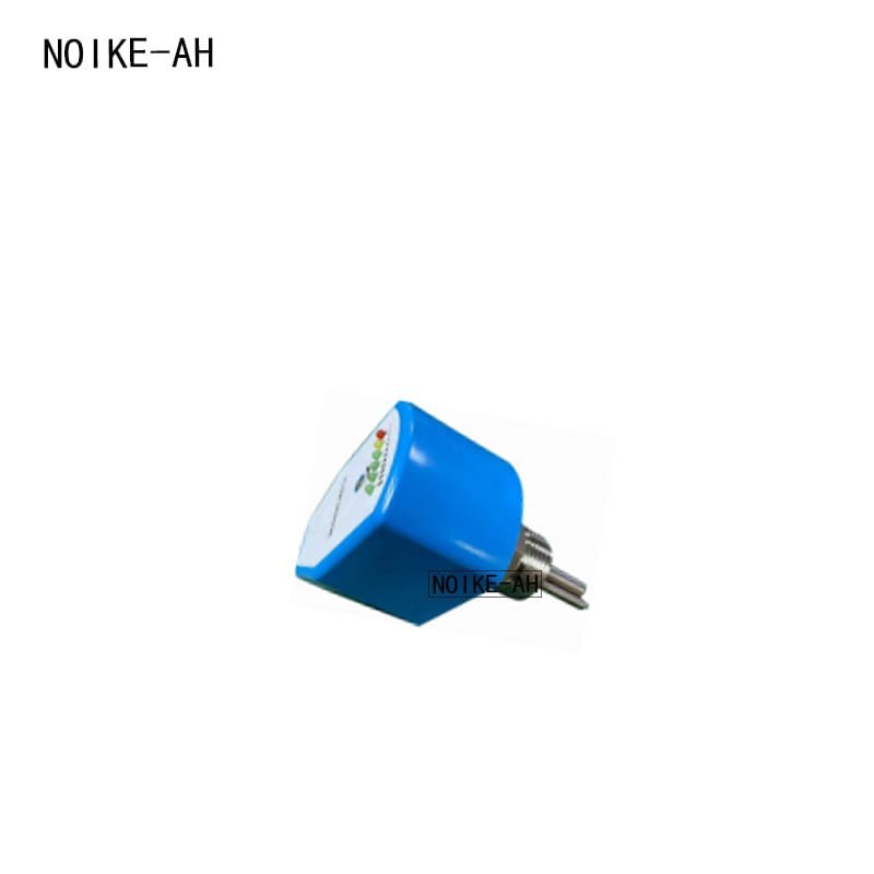
The NOIKE-AH Integrated Flow & Temperature Sensor NK210 Standard Series offers PNP, NPN and relay output options according to the supplied product specifications.
| Parameter | NK210 Specification |
|---|---|
| Output options | PNP / NPN / relay |
| Switching logic | NO / NC configurable |
| PNP/NPN load capacity | 500 mA at 24 VDC |
| Relay load capacity | 60 W |
| Flow switching | Adjustable upper/lower flow thresholds |
| Display | 0.96-inch OLED showing flow, trend and switch status |
| Pressure rating | 100 bar; 300 bar optional |
| Protection | IP67; reverse-polarity, short-circuit and overload protection |
| Power supply | 24 VDC ±20% |
| Connection | M12 connector or 2 m cable (default) |
The NK210 can be considered for applications such as cooling-water monitoring, hydraulic systems, cutting-fluid circulation, lubrication and pump dry-run protection.
Confirm the output variant, switching logic, electrical load and PLC input compatibility with the factory before ordering.
Product page: Integrated Flow & Temperature Sensor NK210
8. Frequently Asked Questions
How do I choose PNP or NPN for a PLC flow switch?
Check the PLC input module. A compatible sinking input arrangement with common at 0 V typically uses a PNP output. A compatible sourcing input arrangement with common at +24 V typically uses an NPN output.
What is the difference between PNP, NPN and relay outputs?
PNP supplies positive voltage to the load, NPN pulls the signal toward 0 V, and a relay switches contacts. The appropriate choice depends on the PLC input, circuit voltage, load and isolation requirements.
What do NO and NC mean on a flow switch?
NO means Normally Open and NC means Normally Closed. They describe the normal state of a contact or configured output logic. Confirm the manufacturer’s reference condition before wiring.
Is NC always safer than NO for pump dry-run protection?
No. NC is often useful in de-energize-to-trip designs, but safety depends on the complete circuit, the switch’s state definitions, power-loss behavior and PLC logic. Test the actual fault response before commissioning.
Can a relay flow switch output connect to a PLC?
Yes, provided the relay contact rating and PLC input circuit are compatible. A typical arrangement uses COM and NO or NC to switch a suitable control voltage to the input.
Does the NK210 support both PNP and NPN outputs?
The supplied NK210 specifications list PNP, NPN and relay as output options, with configurable NO/NC logic. Confirm the specific ordered configuration with the manufacturer.
9. Conclusion
Selecting the correct flow switch output is essential for reliable PLC integration. PNP and NPN outputs must match the PLC input circuit, while relay outputs provide contact-based switching within specified electrical limits. NO and NC must be evaluated separately from the output technology.
For low-flow alarms and pump protection, verify the normal state, power-loss behavior, broken-wire response and PLC program before commissioning.
The NOIKE-AH NK210 offers PNP, NPN and relay options for industrial flow monitoring. Confirm the required output configuration and wiring diagram for the selected model.
Need Help Selecting a Flow Switch for Your PLC?
Share your PLC model, input-module type, supply voltage, required output logic and application medium with NOIKE-AH. These details help identify a compatible flow switch configuration.
Email: [email protected]
Website: https://www.noikeah.com/