
How to Select a Flow Switch for Water, Oil, and Hydraulic Systems
Can a Water Flow Switch Be Used for Hydraulic Oil?
One of the most common engineering mistakes in industrial flow monitoring is assuming that a flow switch calibrated for water can be directly applied to oil or hydraulic systems.
This can result in false alarms, missed low-flow detection, and premature equipment failure.
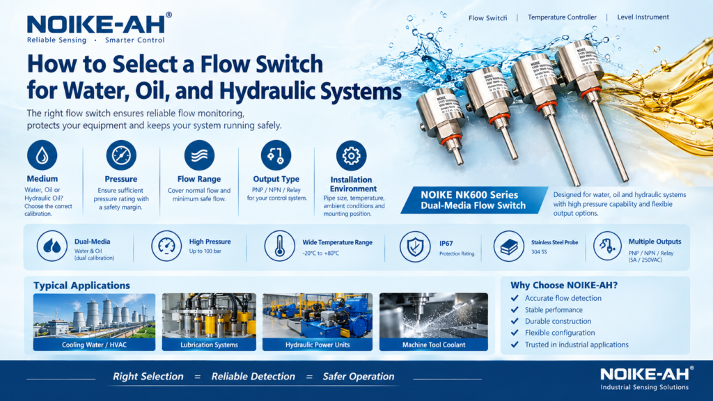
Selecting the correct flow switch requires a systematic evaluation of five key engineering parameters:
- Medium
- Pressure
- Flow Range
- Output Type
- Installation Environment
This guide provides a step-by-step technical framework for selecting flow switches for water, oil, and hydraulic flow monitoring applications.
Can I Use a Water Flow Switch for Hydraulic Oil?
Direct answer: No, not unless the flow switch provides the appropriate calibration for hydraulic oil.
Water and oil have significantly different thermal properties. For thermal dispersion flow switches, the process medium directly affects how heat is transferred away from the sensing element.
A flow switch calibrated for water may therefore produce inaccurate switching behavior when installed in an oil system.
The correct selection must always consider the specific process medium being monitored.
Step 1: Confirm the Process Medium
Why Are Water and Oil Different?
For thermal dispersion flow switches, the process medium is one of the most important selection parameters because it affects the heat transfer rate from the heated sensor.
Thermal Properties: Water vs. Hydraulic / Lube Oil
| Property | Water | Hydraulic / Lube Oil |
|---|---|---|
| Specific Heat Capacity | ~4.18 kJ/(kg·K) | ~1.8–2.2 kJ/(kg·K) |
| Thermal Conductivity | ~0.6 W/(m·K) | ~0.12–0.15 W/(m·K) |
| Viscosity at 40°C | ~0.65 cSt | 30–100+ cSt |
| Heat Transfer Efficiency | High | Significantly Lower |
Engineering Implication
Because oil has a lower specific heat capacity and thermal conductivity than water, it absorbs and carries heat away from the sensor at a different rate.
Therefore, a thermal flow switch must be properly calibrated for the specific medium when switching between water and oil applications.
Typical flow ranges are:
- Water Flow Range: 1–150 cm/s
- Oil Flow Range: 3–300 cm/s
If a water-calibrated switch is used in an oil system, the device may read a higher flow velocity than the actual flow, potentially causing the system to miss a genuine low-flow condition.
Conversely, an oil-calibrated switch used in water may read lower than the actual flow, potentially resulting in nuisance alarms.
Flow Switch Medium Selection Rule
Always confirm that the flow switch provides a dedicated calibration mode or calibrated range for the specific process medium.
Step 2: Confirm the Pressure Rating
The operating pressure determines the required mechanical integrity of the flow switch housing, sensor and sealing system.
The pressure rating should be selected according to the maximum operating pressure of the application, including possible transient pressure spikes.
Typical Application Pressure Requirements
| Application | Typical Pressure Range | Required Rating |
|---|---|---|
| Cooling Water / HVAC | 1–10 bar | ≥ 16 bar |
| Low-Pressure Lubrication | 2–10 bar | ≥ 16 bar |
| High-Pressure Hydraulic (HPU) | 50–150 bar | ≥ 100 bar |
| Machine Tool Coolant | 3–20 bar | ≥ 25 bar |
Pressure Selection Rule
Select a flow switch with at least a 1.5× safety margin above the maximum operating pressure, including transient spikes.
For high-pressure hydraulic systems, a minimum pressure rating of 100 bar is recommended.
Safety Warning
Exceeding the specified pressure rating can cause seal failure, probe ejection, or housing rupture, creating a serious safety hazard.
Step 3: Confirm the Flow Range and Switching Setpoint
The selected flow switch must cover both:
- The normal operating flow
- The minimum flow required for safe operation
The switching setpoint should be selected according to the minimum flow required to protect the equipment.
Flow Switch Selection Process
- Determine the normal flow velocity in the pipe, in cm/s or m/s.
- Determine the minimum flow velocity required for safe operation.
- Confirm that the flow switch measurement range covers both values.
- Set the switching point slightly above the minimum safe flow velocity.
Technical Example
Assume an oil system has:
- Normal oil flow: 80 cm/s
- Minimum safe flow: 25 cm/s
- Required flow range: At least 3–300 cm/s with oil calibration
- Switching setpoint: 30 cm/s
This ensures that the switching point is positioned above the minimum safe flow requirement.
Step 4: Select the Correct Output Type — PNP, NPN, or Relay
The output type determines how the flow switch communicates with the control system.
The three common output configurations are PNP, NPN, and Relay.
PNP vs. NPN vs. Relay Output
| Output Type | Signal Logic | Best For | Typical Load |
|---|---|---|---|
| PNP | Switches +24V to the load | PLC Digital Input (Sourcing) | PLC Input Module |
| NPN | Switches 0V (GND) to the load | PLC Digital Input (Sinking) | PLC Input Module |
| Relay (Dry Contact) | Opens/Closes an isolated contact | Direct motor contactor, safety relay | Up to 5A / 250VAC |
When to Use PNP or NPN
PNP or NPN outputs are suitable when the flow switch signal is processed by a PLC digital input.
The PLC program can then determine the required action, such as:
- Alarm
- Pump shutdown
- Mode change
- Equipment protection
PNP is standard in many European and international PLC systems, including sourcing-input architectures.
NPN is common in some Asian PLC architectures and specific OEM designs.
When to Use Relay Output
Relay output is suitable for hardwired safety interlocks, where the flow switch needs to directly interrupt power to a pump or compressor without relying on PLC logic.
For example, the NC (Normally Closed) relay contact can be wired in series with the pump motor contactor coil. If the flow stops, the relay opens and cuts the power to the contactor coil.
Output Selection Rule
For critical pump protection where a PLC failure must not prevent the shutdown action, a Relay Output flow switch can be used for a hardwired safety interlock.
Step 5: Confirm Installation and Environmental Conditions
Correct flow switch selection also requires verification of the physical installation environment.
| Parameter | What to Check |
|---|---|
| Pipe Size & Material | Ensure the probe length is appropriate for the pipe diameter. Verify material compatibility, such as 304 SS for applicable media. |
| Process Temperature | Confirm that the medium temperature is within the flow switch operating range. |
| Ambient Conditions | Check the required IP rating, such as IP67 for washdown or outdoor environments. |
| Mounting Orientation | Some flow switches require a specific horizontal or vertical mounting orientation. Verify the manufacturer’s datasheet. |
| Upstream/Downstream Distances | Install away from elbows, valves and pumps where possible to reduce the effect of turbulent flow on switching behavior. |
For every application, the actual installation conditions should be checked against the manufacturer’s technical specifications before installation.
The Cost of Incorrect Flow Switch Selection
Incorrect flow switch selection can affect both equipment protection and system availability.
| Selection Error | Potential Consequence |
|---|---|
| Using water calibration for oil | Missed low-flow detection → Pump dry-run → Potential equipment failure |
| Using oil calibration for water | False “No Flow” alarms → Unnecessary downtime |
| Pressure rating too low | Seal failure / housing rupture → Safety hazard |
| Wrong output type | PLC incompatibility / inability to implement hardwired safety shutdown |
| Ignoring coating/slurry limitation | Insulating layer on probe → False readings |
These risks demonstrate why flow switch selection should be based on the actual medium, pressure, flow range, control architecture, and installation environment rather than on flow switch type alone.
Technical Example: NOIKE NK600 Series Dual-Media Flow Switch
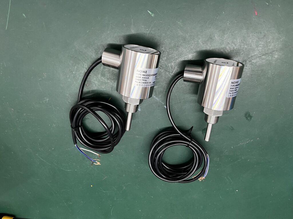
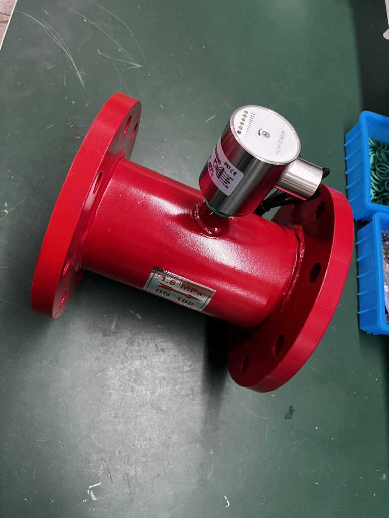
The NOIKE NK600 Series is a thermal dispersion flow switch designed for applications requiring multi-media compatibility, high-pressure capability and flexible output configurations.
NK600 Flow Switch Selection Compatibility
| Selection Parameter | NK600 Specification | Evidence |
|---|---|---|
| Medium | Water AND Oil (dual calibration) | Official Product Page |
| Water Flow Range | 1–150 cm/s | Official Product Page |
| Oil Flow Range | 3–300 cm/s | Official Product Page |
| Operating Pressure | Up to 100 bar | Official Product Page |
| Operating Temperature | -20°C to +80°C | Official Product Page |
| Wetted Material | 304 Stainless Steel | Official Product Page |
| Housing Material | PUR (Polyurethane) | Official Product Page |
| Protection Rating | IP67 | Official Product Page |
| Output Options | PNP / NPN / Relay (5A / 250VAC) | Official Product Page |
| Power Supply | 24 VDC ±20% or 220 VAC ±20% | Official Product Page |
| Warm-up Time | Approx. 15 seconds | Official Product Page |
Engineering Note
The NOIKE NK600 is a flow switch designed for flow/no-flow detection and low-flow alarms.
It is not a precision flow meter intended for continuous measurement or custody transfer.
The NK600 is also not recommended for fluids containing heavy particulates or coating agents that may insulate the sensing probe.
Always verify the compatibility between the process medium and the flow switch before installation.
Frequently Asked Questions About Water, Oil and Hydraulic Flow Switches
Can I use the same thermal flow switch for both water and oil systems?
Yes, but only when the device provides an appropriate dual-media calibration feature.
For example, the NK600 provides separate calibrated ranges for:
- Water: 1–150 cm/s
- Oil: 3–300 cm/s
The correct calibration mode must be selected before installation. Using an incorrect calibration can result in inaccurate switching behavior.
What happens if I install a water flow switch in a hydraulic oil circuit?
A water-calibrated thermal flow switch may indicate a higher flow velocity than the actual oil flow because oil transfers heat less efficiently than water.
As a result, the switch may indicate “Flow OK” even when the actual flow is dangerously low, potentially allowing a pump to continue operating under an unsafe low-flow condition.
How do I choose between PNP, NPN and Relay output?
Use PNP or NPN when the flow switch is connected to a PLC digital input.
Use Relay output when a hardwired safety interlock is required to directly interrupt a pump or compressor control circuit without relying on PLC logic.
For critical pump protection requiring a hardwired shutdown function, Relay output can be used.
What pressure rating do I need for a hydraulic power unit?
First determine the system’s maximum operating pressure, including possible transient pressure spikes.
Then select a flow switch with at least a 1.5× pressure safety margin.
For hydraulic power units operating around 70–100 bar, a flow switch rated at 100 bar minimum is required according to the selection criteria described above.
How Does Pipe Size Affect Flow Switch Selection?
The sensing probe must be long enough to reach the appropriate flow region within the pipe.
For very large pipes, such as DN200 and above, a standard insertion probe may not reach the optimal sensing zone.
Therefore, verify the probe length and installation position against the pipe diameter before ordering.
Flow Switch Selection Checklist
Before selecting a flow switch for a water, oil or hydraulic application, verify the following five parameters:
1. Medium
Is the flow switch calibrated for the actual process medium?
2. Pressure
Does the pressure rating provide sufficient margin above the maximum operating pressure and transient spikes?
3. Flow Range
Does the available flow range cover both normal flow and the minimum safe flow?
4. Output Type
Is the output compatible with the PLC, control system or hardwired safety interlock?
5. Installation Environment
Are the pipe size, process temperature, ambient conditions, mounting orientation and upstream/downstream installation requirements suitable?
A flow switch should be selected only after all five parameters have been verified against the application requirements and manufacturer‘s technical specifications.
Conclusion
Selecting a flow switch for water, oil or hydraulic systems requires more than simply matching the pipe size or nominal flow rate.
The process medium, pressure rating, flow range, output configuration and installation environment all affect the suitability of the device.
In particular, water and oil should not be treated as interchangeable media for thermal dispersion flow switches. The correct medium calibration must be selected to achieve reliable flow/no-flow detection and low-flow protection.
For industrial applications requiring water and oil compatibility, high-pressure capability and flexible output options, the NOIKE NK600 Series provides a dual-media flow-switch solution based on the specifications listed above.
Always verify the complete application conditions and product datasheet before installation.
Internal References & Resources:
Internal References & Resources:
1.Core Concepts:
Thermal Flow Switch Principle & Applications
2.Technology Comparison:
Why Mechanical Flow Switch Failure in Oil Systems? Mechanical vs. Thermal Flow Switch
3.Selection Guide
How to Select a Flow Switch for Water, Oil, and Hydraulic Systems
4.Product Specifications:



