
Why Mechanical Flow Switch Failure in Oil Systems? Mechanical vs. Thermal Flow Switch
Why Do Mechanical Flow Switches Fail in Oil Systems?
Direct Answer
Mechanical flow switches can stick, seize, or generate false alarms in lubrication and hydraulic oil systems because their operation depends on moving mechanical components such as paddles, pistons, springs, or magnetic targets. Changes in oil viscosity, particulate contamination, sludge, varnish, and high-pressure transients can interfere with these moving components and cause unreliable switching.
Thermal dispersion flow switches provide an alternative by detecting flow through the calorimetric principle, or heat transfer, rather than mechanical movement. Because they have no moving parts, they eliminate mechanical sticking and seizure associated with paddles, pistons, and springs.
Key Takeaways
- Mechanical flow switches depend on physical movement and can be affected by oil viscosity, contamination, and pressure transients.
- Cold oil can become highly viscous and reduce the force available to move a mechanical actuator.
- Particles, varnish, and sludge can cause paddles and pistons to stick or seize.
- High-pressure shock and repeated transients can contribute to fatigue or mechanical damage.
- Thermal dispersion flow switches use heat transfer rather than mechanical movement to detect oil flow.
- The NOIKE NK600 Series provides an oil flow range of 3–300 cm/s and operating pressure up to 100 bar.
- Thermal flow switches are suitable for many oil-monitoring applications but should not be used where heavy deposits can coat and insulate the sensing probe.
What Causes Mechanical Flow Switch Failure in Oil Systems?
In industrial lubrication and hydraulic circuits, flow switches are important safety devices.
They can be used to verify that bearings receive adequate lubrication before a compressor starts or to help ensure that a hydraulic pump does not operate without sufficient fluid flow.
However, maintenance engineers frequently encounter a persistent problem:
Mechanical flow switches may stick, seize, or generate false alarms in oil systems.
If a paddle, piston, or magnetic flow switch repeatedly fails in a lubrication oil console or high-pressure hydraulic power unit (HPU), the underlying problem is often associated with the mechanical operating principle and the conditions of the oil system.
Three engineering factors are particularly important:
- Kinematic viscosity fluctuations
- Particulate contamination and sludge
- High-pressure shock and transients
1. Kinematic Viscosity Fluctuations
Unlike water, the viscosity of hydraulic and lubricating oil can change significantly with temperature.
Because mechanical flow switches rely on fluid force to move an actuator, changes in oil viscosity can affect the mechanical switching behavior.
Cold Startup
When oil is cold, its viscosity increases and the fluid becomes thicker.
A mechanical paddle or piston calibrated around normal operating conditions may require more flow force to move the actuator.
If the available flow force is insufficient during startup, the switch may fail to reach its expected position and can generate a false “No Flow” alarm.
Hot Operation
As oil temperature increases, viscosity decreases and the oil becomes thinner.
The change in fluid drag can alter the force acting on the mechanical sensing element.
Under marginal operating conditions, this can contribute to intermittent switching or an unexpected change in the switch state.
Therefore, oil temperature and viscosity should be considered when applying mechanical flow switches in lubrication and hydraulic systems.
2. Particulate Contamination and Sludge
Hydraulic and lubrication oils are not always completely free of contamination.
Depending on system condition, the oil may contain microscopic wear particles, seal debris, varnish, and sludge generated by oil oxidation.
These contaminants can interfere with moving mechanical components.
Paddle Flow Switch
In a paddle-type flow switch, contamination can accumulate around the hinge or pivot.
Over time, deposits can restrict paddle movement and eventually cause the paddle to stick.
Piston Flow Switch
In a piston-type flow switch, particulate contamination can act as an abrasive.
Particles may score the piston bore and contribute to increased friction or piston seizure.
Once a mechanical flow switch becomes stuck, the device may no longer provide reliable flow protection.
For example, if the switch remains in the “Flow” position after actual flow has been lost, the control system may not receive the required protection signal.
This can expose the pump, bearings, or other downstream equipment to damage.
3. High-Pressure Shock and Transients
High-pressure hydraulic systems, often operating at 50–100+ bar, can experience pressure spikes and transient effects when valves open or close rapidly.
Mechanical components such as:
- Plastic paddles
- Springs
- Magnetic targets
- Moving pistons
- Mechanical linkages
can be subjected to repeated mechanical stress.
Over time, these pressure transients can contribute to mechanical fatigue, deformation, or component failure.
For this reason, the pressure rating and mechanical construction of the flow switch should be considered carefully when selecting a device for high-pressure hydraulic applications.
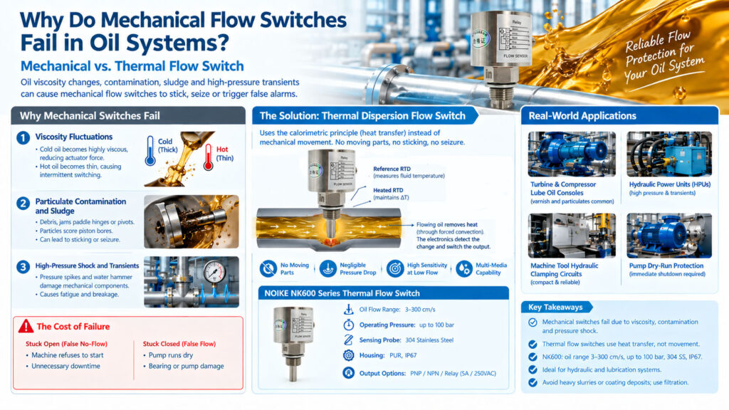
What Happens When a Mechanical Flow Switch Fails?
Mechanical flow switch failures in oil systems can generally lead to two major types of problems.
Stuck Open — False No-Flow
The switch incorrectly indicates that there is insufficient flow.
The machine may refuse to start because the control system interprets the signal as inadequate lubrication or flow.
This can result in:
- Unnecessary machine shutdown
- Production downtime
- Maintenance intervention
- Repeated troubleshooting
Stuck Closed — False Flow
The switch incorrectly indicates that adequate flow is present.
For example, the pump may lose prime or a filter may become blocked while the switch remains in the flow position.
The system can then continue operating without adequate lubrication or hydraulic flow.
Potential consequences include:
- Bearing damage
- Pump damage
- Hydraulic pump cavitation
- Equipment downtime
- Increased maintenance costs
For safety-critical applications, the failure behavior of the flow switch should therefore be considered as part of the overall protection system.
Engineering Solution: Eliminating Moving Parts
One approach to reducing mechanical sticking problems is replacing a mechanical flow switch with a thermal dispersion flow switch.
Thermal flow switches use the calorimetric principle, or heat transfer, to detect fluid movement.
Instead of relying on a paddle, piston, spring, or magnetic target, the sensing probe measures the thermal effect created when flowing oil carries heat away from a heated sensing element.
Because the sensing principle does not depend on mechanical movement, the switch eliminates mechanical failure mechanisms associated with:
- Paddle sticking
- Piston seizure
- Spring fatigue
- Mechanical linkage wear
- Mechanical movement caused by pressure shock
This makes thermal dispersion technology particularly useful for flow monitoring in oil and hydraulic systems where mechanical switching components may be exposed to challenging operating conditions.
How Does a Thermal Flow Switch Detect Oil Flow?
A thermal dispersion flow switch typically uses temperature sensors and a heating element within the sensing probe.
The system establishes a temperature difference between the heated sensing element and the surrounding process fluid.
When the oil is stationary, heat remains concentrated around the sensing element.
When oil begins to flow, the moving fluid removes heat from the heated element through forced convection.
As flow velocity increases, the cooling effect increases.
The electronic circuit monitors this thermal change and determines whether the measured condition has reached the configured switching point.
The key difference is therefore:
Mechanical flow switch:
Fluid force → mechanical movement → switching action
Thermal dispersion flow switch:
Fluid movement → heat transfer → electronic switching action
Mechanical vs. Thermal Flow Switches for Oil Applications
| Failure Mode | Mechanical Switch (Paddle/Piston) | Thermal Dispersion Switch |
|---|---|---|
| Viscosity Changes | Higher risk because mechanical force varies with oil viscosity | Lower mechanical risk; calibrated for the thermal properties of oil |
| Particulate Buildup | Higher risk because debris can interfere with moving components | Lower mechanical risk because the probe has no moving parts |
| Pressure Shock | Higher risk of mechanical fatigue or component damage | Lower mechanical risk because there are no moving mechanical components |
| Maintenance | May require cleaning and recalibration | Virtually none; probe inspection/cleaning may be required during scheduled maintenance |
The comparison highlights the main engineering difference between the two technologies.
Mechanical switches depend on physical movement, while thermal dispersion switches determine flow through heat transfer.
Key Advantages of Thermal Flow Switches in Oil Systems
No Moving Parts
The thermal sensing principle eliminates mechanical paddles, pistons, springs, and other moving components.
This reduces the possibility of mechanical seizure caused by contamination or changes in oil viscosity.
High-Pressure Application Capability
Thermal flow switches can be designed with robust stainless-steel sensing probes for demanding hydraulic applications.
The NK600 Series, for example, has an operating pressure rating of up to 100 bar.
Oil-Specific Calibration
Thermal flow detection depends on the thermal characteristics of the process medium.
The NK600 Series provides a dedicated oil flow range of:
3–300 cm/s
This allows the instrument to be configured specifically for oil applications rather than relying on a standard water-based calibration.
Reduced Mechanical Maintenance
Because there are no moving mechanical components inside the sensing mechanism, there is no paddle or piston that needs to move freely during normal operation.
Routine maintenance should still include appropriate inspection of the sensing probe and process conditions.
Real-World Applications for Thermal Flow Switches
Thermal dispersion technology can be applied to a range of industrial oil and hydraulic flow-monitoring applications.
1. Turbine and Compressor Lube Oil Consoles
Lubrication systems require reliable oil flow to protect bearings and other critical components.
Thermal flow switches can be used to monitor lubrication flow where oil varnish and particulate contamination may affect mechanical switching mechanisms.
2. Hydraulic Power Units (HPUs)
Hydraulic power units can operate under high pressure and may experience pressure transients.
A thermal flow switch provides flow monitoring without mechanical paddles or pistons that can be affected by pressure shock or contamination.
3. Machine Tool Hydraulic Clamping Circuits
Machine tools may have compact hydraulic circuits where reliable flow monitoring is required within limited installation space.
Thermal flow switches can provide electronic flow detection without a mechanical actuator.
4. Pump Dry-Run Protection
A flow switch can be used as part of a pump protection system.
If the required flow condition is lost, the switch can provide a control signal to initiate pump shutdown.
This can help protect pumps from operating under inadequate flow conditions.
Recommended Instrument: NOIKE NK600 Series Thermal Flow Switch
The NOIKE NK600 Series Thermal Flow Switch is a thermal dispersion flow switch designed for demanding liquid-flow monitoring applications.
Its solid-state sensing principle eliminates moving components that can stick or seize in oil systems.
NK600 Series Engineering Specifications
No Moving Parts
The solid-state thermal sensing design eliminates mechanical moving components and therefore reduces the risk of mechanical seizure associated with oil sludge, contamination, and viscosity-related mechanical binding.
High-Pressure Durability
The NK600 Series is rated for operating pressures up to:
100 bar
This makes it suitable for high-pressure hydraulic circuits and other demanding liquid-flow monitoring applications.
Oil-Specific Calibration
The NK600 Series provides a dedicated oil flow range of:
3–300 cm/s
This range is designed for oil applications based on the thermal characteristics of the medium.
304 Stainless Steel Sensing Probe
The sensing probe is constructed from:
304 Stainless Steel
The product also uses a rugged PUR housing and provides IP67 protection for demanding industrial environments.
Direct Control Output
The NK600 Series is available with relay output options.
The relay version provides:
5 A / 250 VAC
This allows the flow switch to be integrated into control circuits and used for applications such as pump shutdown.
Engineering Note: Application Limitations
Although the NK600 Series eliminates mechanical seizure, thermal dispersion technology still has application limitations.
It is not recommended for heavy slurries or fluids containing high concentrations of magnetic iron particles that can physically coat and insulate the sensing probe.
A coating on the sensing probe can interfere with heat transfer between the sensor and process medium and may result in an incorrect flow indication.
For heavily contaminated hydraulic systems, an upstream filter is recommended as part of the overall system design.
The device also requires an initial warm-up period of approximately 15 seconds after power-on to stabilize the internal heating element.
How to Choose a Flow Switch for Hydraulic Oil
Before replacing a mechanical flow switch with a thermal flow switch, engineers should evaluate several application parameters.
1. Oil Type
Confirm the type of hydraulic or lubrication oil and its expected thermal characteristics.
2. Operating Temperature
Determine the normal cold-start and operating temperatures because oil viscosity varies with temperature.
3. Flow Velocity
Confirm the minimum, normal, and maximum flow velocity.
For the NK600 Series, the dedicated oil range is:
3–300 cm/s
4. Operating Pressure
Verify the maximum system pressure and potential pressure transients.
The NK600 Series is rated up to:
100 bar
5. Contamination Level
Evaluate the amount and type of particulate contamination, sludge, varnish, and other deposits in the oil.
Heavy deposits that coat the sensing probe can affect thermal measurement.
6. Required Output
Determine whether the control system requires:
- PNP
- NPN
- Relay
For direct control applications, a suitable relay output can be integrated into the pump control circuit according to the system’s electrical design.
7. Required Protection Function
Determine whether the flow switch is being used for:
- Lubrication monitoring
- Hydraulic flow monitoring
- Pump dry-run protection
- Low-flow alarm
- Pump shutdown
- Equipment protection
The required switching logic and fail-safe behavior should be defined as part of the complete control-system design.
Frequently Asked Questions
Can I clean a stuck mechanical flow switch to fix it permanently?
Cleaning a stuck paddle or piston can restore operation temporarily, but it does not eliminate the underlying causes of mechanical sticking.
If particulates, varnish, sludge, or viscosity-related mechanical loading remain in the system, the mechanical components may become stuck again.
For applications where repeated mechanical seizure is a persistent problem, replacing the mechanical switching principle with a solid-state thermal flow switch can eliminate the moving-part failure mechanism.
Will a thermal flow switch work in dirty hydraulic oil?
Yes, provided the oil does not contain heavy deposits that coat the sensing probe.
Thermal flow switches have no moving parts that can become jammed by normal particulate contamination.
However, thick sludge or other deposits that physically coat the probe can act as an insulating layer and interfere with heat transfer.
Therefore, the cleanliness of the oil and the possibility of sensor coating should be evaluated during application selection.
How do I wire a flow switch for automatic pump shutdown?
For critical pump protection, a flow switch with an appropriate relay output can be integrated into the pump control circuit.
For example, the NK600 relay version provides a 5 A / 250 VAC relay output.
The switching logic should be designed so that loss of the required flow condition generates the intended pump shutdown signal.
For a typical control architecture, the relay contact can be incorporated into the motor contactor control circuit, subject to the contactor coil voltage, electrical ratings, safety requirements, and the specific control-system design.
The final wiring should always be verified against the actual electrical schematic and applicable safety requirements.
Does cold oil affect thermal flow switch accuracy?
Cold oil significantly affects viscosity, which can directly influence the mechanical behavior of conventional paddle or piston flow switches.
Thermal flow switches use a different detection principle based on heat transfer.
The thermal behavior of the selected oil and the instrument calibration must still be considered. As long as the oil type remains consistent and the device is appropriately calibrated for the application, changes in viscosity do not create the same mechanical binding mechanism found in a moving-part flow switch.
For the NK600 Series, the dedicated oil flow range is 3–300 cm/s.
Conclusion
Mechanical flow switch failure in hydraulic and lubrication systems is often associated with the physical conditions under which the mechanical sensing components operate.
Oil viscosity fluctuations, particulate contamination, sludge, varnish, and pressure transients can interfere with paddles, pistons, springs, and other moving components.
When repeated sticking or seizure becomes a maintenance problem, a thermal dispersion flow switch provides an alternative sensing method that does not depend on mechanical movement.
By using the calorimetric principle, the thermal flow switch detects the heat-transfer effect created by moving oil.
The NOIKE NK600 Series Thermal Flow Switch provides:
- No moving parts
- Oil-specific flow range of 3–300 cm/s
- Operating pressure up to 100 bar
- 304 stainless steel sensing probe
- PUR housing
- IP67 protection
- Relay output options up to 5 A / 250 VAC
- Application suitability for hydraulic and lubrication flow monitoring
However, heavy slurries and fluids that create an insulating coating on the probe should be avoided, and an appropriate upstream filtration system should be considered for heavily contaminated oil circuits.
For applications involving hydraulic power units, turbine and compressor lubrication systems, machine-tool hydraulics, and pump protection, the selection between mechanical and thermal flow-switch technology should be based on the actual oil properties, flow conditions, pressure, contamination level, and required protection function.
Request a Thermal Flow Switch for Your Oil System
If you are experiencing repeated mechanical flow switch sticking, seizure, false alarms, or maintenance problems in a hydraulic or lubrication system, provide the following application information for flow-switch selection:
- Medium: hydraulic oil / lubrication oil
- Flow range
- Operating pressure
- Operating temperature
- Pipe size
- Required switching point
- Required output: PNP / NPN / Relay
NOIKE-AH — Professional Flow Instrument Manufacturer
Internal References & Resources:
Internal References & Resources:
1.Core Concepts:
Thermal Flow Switch Principle & Applications
2.Technology Comparison:
Why Mechanical Flow Switch Failure in Oil Systems? Mechanical vs. Thermal Flow Switch
3.Selection Guide
How to Select a Flow Switch for Water, Oil, and Hydraulic Systems
4.Product Specifications:



