Differential Pressure Level Transmitter Troubleshooting: Fault Diagnosis, Inspection, and Corrective Actions with Practical Engineering Case Studies
Introduction
Differential pressure (DP) level transmitters are widely used for continuous level measurement in the petroleum, chemical, power generation, pharmaceutical, metallurgy, and water treatment industries. They are commonly installed on storage tanks, process vessels, reactors, boiler drums, and other industrial equipment.
DP level transmitters offer a well-established measurement principle, relatively simple construction, broad application suitability, and convenient integration with industrial automation and control systems.
However, during actual operation, measurement performance can be affected by various factors, including impulse line blockage, changes in process fluid density, gas or liquid accumulation in impulse lines, zero-point drift, incorrect valve positions, and transmitter malfunctions.
These problems may cause abnormal level readings, including:
- Incorrectly high or low level indications
- Unstable or fluctuating level readings
- A level indication that remains fixed
- Delayed response to actual level changes
- Inconsistency between the indicated level and the actual process level
When a DP level transmitter develops a fault, the transmitter itself should not automatically be considered the source of the problem.
A systematic troubleshooting approach should be followed, starting with process conditions and progressing through the impulse piping, valve manifold, transmitter, electrical signal loop, and control system.
This article explains the operating principles of DP level transmitters, identifies common failure modes, and provides practical inspection and troubleshooting procedures. It also presents typical industrial engineering scenarios to help instrumentation engineers and maintenance personnel diagnose and resolve level measurement problems.
1. Operating Principle of Differential Pressure Level Transmitters
A differential pressure level transmitter determines liquid level by measuring the pressure difference generated by the liquid column inside a vessel.
The fundamental relationship between hydrostatic pressure and liquid height is:
P = rho * g * h
Where:
- P = Hydrostatic pressure generated by the liquid column (Pa)
- rho = Liquid density (kg/m3)
- g = Gravitational acceleration, approximately 9.81 m/s2
- h = Liquid column height (m)
For an open tank, the low-pressure side is normally exposed to atmospheric pressure, while the high-pressure side is connected to the bottom of the vessel.
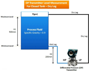
For a closed vessel, the gas pressure above the liquid must also be considered. A differential pressure transmitter measures the pressure difference between the bottom and top connections to compensate for changes in vapor-space pressure.
1.1 Level Measurement in Open Vessels
In an open vessel, the low-pressure side is generally vented to atmosphere, while the high-pressure side is connected to the bottom of the tank.
The differential pressure is calculated as follows:
DP = rho * g * h
When the liquid density remains constant, the differential pressure is directly proportional to the liquid level.
1.2 Level Measurement in Closed Vessels
In a closed vessel, pressure exists in the vapor space above the liquid. If only the pressure at the bottom of the vessel is measured, changes in vapor-space pressure will affect the measurement.
Therefore, a differential pressure transmitter is typically installed with:
- High-pressure side (HP) connected to the bottom of the vessel.
- Low-pressure side (LP) connected to the top of the vessel.
Under ideal measurement conditions:
DP = P_HP – P_LP = rho * g * h
Where:
- P_HP = Pressure at the high-pressure side
- P_LP = Pressure at the low-pressure side
- DP = Differential pressure
- rho = Process liquid density
- g = Gravitational acceleration
- h = Liquid column height
By subtracting the vapor-space pressure from the bottom pressure, the transmitter can determine the liquid level.
Technical Note: In actual industrial installations, additional factors must be considered, including wet-leg or dry-leg impulse piping, liquid column height, differences in fluid density, transmitter elevation, remote diaphragm seals, and capillary fill-fluid characteristics.
The actual measuring range and zero elevation or suppression must be calculated according to the specific installation configuration. The standard open-tank formula should not be applied indiscriminately to every installation.
2. Common Differential Pressure Level Transmitter Faults and Diagnostic Methods
DP level transmitter faults generally appear as abnormal measurement values, unstable signals, or complete measurement failure.
During troubleshooting, the first step is to determine whether the process level has actually changed. The measurement system should then be inspected systematically.
2.1 Level Reading Is Higher Than the Actual Level
Typical Symptoms
- The control room indicates a higher level than the actual field level.
- A persistent deviation exists between the indicated and actual levels.
- The transmitter reading gradually increases even though the process level remains relatively stable.
Possible Causes
- Liquid accumulation in the low-pressure impulse line, resulting in an additional hydrostatic pressure head.
- Abnormal pressure transmission through the high-pressure impulse line.
- Zero-point drift or incorrect zero adjustment.
- Incorrect transmitter range or zero elevation/suppression settings.
- Changes in wet-leg liquid column height or density.
- Abnormal installation conditions or fill-fluid problems in remote diaphragm seal capillary systems.
Inspection and Corrective Actions
- Compare the transmitter reading with a local level gauge, sight glass, or another reliable measurement method.
- Inspect the high- and low-pressure impulse lines for liquid accumulation, leakage, and blockage.
- Verify the transmitter range, zero settings, and lower and upper range values.
- Check the wet-leg liquid column height and condensate pot conditions against the design requirements.
- Where process isolation and safety conditions permit, perform zero verification and calibration in accordance with the instrument maintenance procedure.
It is important to note that liquid accumulation in the low-pressure impulse line does not always cause a higher level indication. The direction of the measurement error depends on the actual installation configuration, liquid column height, and location of the accumulated liquid.
2.2 Level Reading Is Lower Than the Actual Level
Typical Symptoms
- The actual vessel level is normal, but the control room indicates a lower value.
- The indicated level changes less than the actual level.
- Abnormal measurement deviations occur as process temperature or pressure changes.
Possible Causes
- Blockage or leakage in the high-pressure impulse line.
- Gas accumulation in the high-pressure impulse line, affecting pressure transmission.
- Abnormally increased pressure on the low-pressure side.
- A difference between the actual process fluid density and the design density.
- Incorrect transmitter zero or range settings.
- Abnormal conditions in remote diaphragm seals or capillary systems.
Inspection and Corrective Actions
- Check whether the high-pressure impulse line is clear.
- Inspect the low-pressure side for additional pressure or abnormal liquid head.
- Verify the actual process fluid density against the design parameters.
- Check the transmitter differential pressure reading and output current.
- Recalculate the measurement range and zero elevation or suppression according to the actual installation configuration.
2.3 Unstable or Fluctuating Level Readings
Typical Symptoms
- The level value continuously fluctuates in the control room.
- The actual field level remains relatively stable, while the transmitter signal fluctuates significantly.
- Signal fluctuations are associated with pump startup, valve operation, or process pressure changes.
Possible Causes
- Actual process fluctuations or liquid surface disturbances.
- Gas bubbles, gas accumulation, or liquid accumulation inside the impulse lines.
- Mechanical vibration caused by improperly supported impulse piping.
- Partial blockage or intermittent obstruction at the pressure tapping point.
- Inappropriate transmitter damping settings.
- Loose electrical connections, poor grounding, or electromagnetic interference.
- Unstable power supply or signal loop conditions.
Inspection and Corrective Actions
- Observe whether the actual liquid level fluctuates at the same time.
- Check for pressure pulsations caused by pumps, compressors, or other operating equipment.
- Inspect impulse line connections, supports, and pressure tapping points.
- Check the power supply, terminal connections, shielding, and grounding.
- Adjust transmitter damping according to process response requirements. Increasing damping alone should not be used to conceal an actual process or instrument fault.
2.4 Level Reading Remains Fixed
Typical Symptoms
- The process level changes, but the transmitter reading remains unchanged.
- The level indication stays at a constant value for an extended period.
- The control system reading differs significantly from the actual field level.
Possible Causes
- Complete blockage of the high- or low-pressure impulse line.
- A pressure tapping valve is closed or incorrectly positioned.
- Incorrect operating status of the three-valve or five-valve manifold.
- Failure of the transmitter sensor.
- Fixed or abnormal transmitter output.
- DCS input channel, signal wiring, or configuration problems.
Inspection and Corrective Actions
- Verify the positions of all relevant field valves.
- Inspect the high- and low-pressure impulse lines for blockage.
- Use an appropriate pressure calibration device to check the relationship between transmitter input pressure and output signal.
- Check the transmitter diagnostic status and alarm information.
- Verify the 4-20 mA output and the DCS analog input channel.
- Determine whether the fault originates from mechanical blockage, transmitter failure, or the control system.
2.5 Transmitter Reading Does Not Match the Actual Liquid Level
This type of fault requires particular attention to the measurement principle, installation configuration, and process parameters.
For example, when the actual liquid density changes, the differential pressure may also change even if the liquid height remains constant.
For a DP level transmitter configured with a fixed design density:
h = DP / (rho * g)
If the actual liquid density differs from the design density, the level calculated using the original transmitter range will contain a systematic measurement error.
Corrective Actions
- Verify the actual process fluid density.
- Check changes in process temperature and concentration.
- Review the instrument range calculation and original design parameters.
- Inspect transmitter elevation and the liquid column in the impulse lines.
- Recalculate the measuring range if necessary.
3. Key Inspection Points in Differential Pressure Level Transmitter Troubleshooting
In actual industrial applications, a DP level transmitter fault does not necessarily originate in the transmitter itself.
The impulse lines, valve manifold, pressure tapping points, and installation configuration can also affect measurement accuracy.
The following components should be carefully inspected during troubleshooting.
3.1 High- and Low-Pressure Impulse Lines
Impulse lines transmit process pressure to the differential pressure transmitter. Their condition directly affects measurement accuracy.
Key inspection points include:
- Blockage, leakage, corrosion, or mechanical deformation.
- Gas accumulation or liquid accumulation.
- Improper high points or low points in the impulse piping.
- Whether the fluid conditions in both impulse lines meet the design requirements.
- Insulation and heat tracing conditions.
- Freezing, crystallization, or process fluid deposition.
For liquid measurement, particular attention should be paid to gas accumulation in the impulse lines.
For gas measurement, condensate accumulation should be carefully checked.
For closed-vessel applications, the correct connections of the high- and low-pressure sides must also be verified.
3.2 Three-Valve and Five-Valve Manifolds
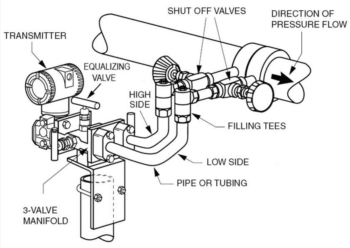
A typical three-valve manifold consists of two isolation valves and one equalizing valve. It is used to isolate the transmitter and equalize the pressure between the two sides.
Common field problems include:
- The equalizing valve is not fully closed.
- The high- or low-pressure isolation valve is not fully open.
- Internal leakage within the valves.
- Contamination or foreign material inside the manifold.
- Incorrect valve restoration after maintenance.
For example, if the equalizing valve remains open, the high- and low-pressure sides may become connected through the manifold. This prevents the actual differential pressure from being correctly transmitted to the sensor, resulting in an abnormal level indication.
Inspection Requirements: Valve operation must follow the manufacturer’s specified procedure. Never dismantle a pressurized manifold or loosen process connections without proper isolation and depressurization.
3.3 Differential Pressure Transmitter
The following items should be inspected:
- Check whether the transmitter has any diagnostic alarms.
- Verify whether the pressure sensor responds correctly to pressure changes.
- Confirm that the zero and range settings are correct.
- Inspect the electronic components for damage or moisture ingress.
- Verify whether the output signal meets the 4-20 mA requirements.
- Confirm consistency between the local display and output signal.
If the input differential pressure changes but the transmitter output does not respond accordingly, further inspection of the pressure sensor, electronic module, output configuration, and signal loop is required.
3.4 Electrical Wiring and DCS Control System
If the local transmitter display is normal but the control room indication is abnormal, troubleshooting should focus on the signal transmission and control system.
Inspection items include:
- Stability of the 24 V DC power supply.
- Signal cable disconnection or short circuit.
- Loose terminal connections.
- Shielding and grounding arrangements.
- Condition of safety barriers and signal isolators.
- DCS analog input channel status.
- Correct engineering range, measurement units, and signal scaling configuration.
For a standard 4-20 mA signal, the measurement relationship is generally as follows:
| Output Current | Measurement Percentage |
|---|---|
| 4 mA | 0% |
| 8 mA | 25% |
| 12 mA | 50% |
| 16 mA | 75% |
| 20 mA | 100% |
However, actual transmitters may use zero elevation, zero suppression, reverse ranging, or other output configurations. The actual transmitter configuration must always be verified before making a diagnosis.
4. Practical Engineering Case Studies: Typical Differential Pressure Level Transmitter Faults
The following cases are engineering scenarios based on common industrial equipment configurations and established fault mechanisms.
Since no original project maintenance records or field measurement data have been provided, the equipment parameters and symptoms are illustrative rather than verified measurements from a specific industrial installation.
Their purpose is to demonstrate how field evidence can be used to identify the source of a fault, rather than to present assumptions as actual accident records.
Case Study 1: Low Level Indication in a Closed Storage Tank
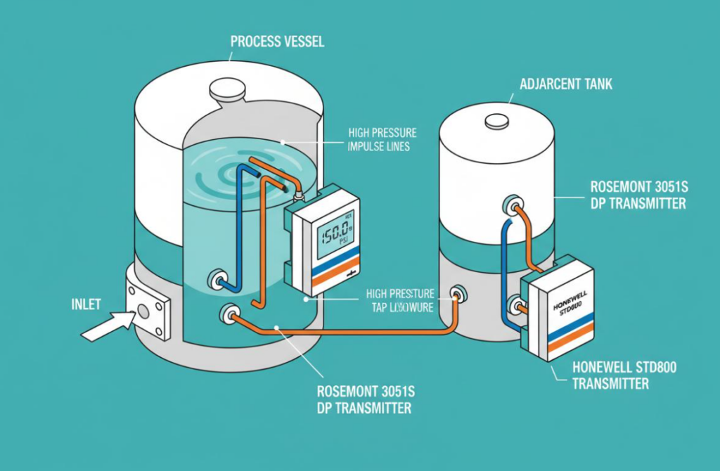
1. Field Symptoms
A differential pressure level transmitter is installed on a closed storage tank in an industrial process unit.
During operation, operators observe the following:
- The control room indicates a lower level than the local reference measurement.
- Tank inlet and outlet operating conditions remain relatively stable.
- The level indication does not correspond to the actual process operating trend.
- No obvious hardware fault alarm is displayed by the transmitter.
The initial suspicion is zero-point drift or an incorrect transmitter range setting.
2. Fault Analysis
The transmitter zero should not be adjusted immediately.
A closed-vessel DP level measurement system consists of the high-pressure side, low-pressure side, impulse lines, and differential pressure transmitter.
If the liquid column condition in the low-pressure impulse line changes, the measured differential pressure will also change.
This is particularly important in wet-leg installations, where the low-pressure side must maintain a specified liquid column height.
If the condensate level decreases, the liquid column becomes discontinuous, or leakage occurs, the hydrostatic pressure on the low-pressure side may change.
For a typical installation with the high-pressure side connected to the vessel bottom and the low-pressure side connected through a wet leg, the differential pressure can be expressed as:
DP = (rho_p * g * h_p) – (rho_w * g * h_w)
Where:
- rho_p = Density of the process liquid.
- h_p = Process liquid column height.
- rho_w = Density of the wet-leg liquid.
- h_w = Wet-leg liquid column height.
If the wet-leg liquid column height changes, the differential pressure measured by the transmitter will change even when the actual tank level remains constant.
3. Field Inspection Procedure
- Check the low-pressure impulse line for leakage.
- Inspect the condensate pot and wet-leg liquid column condition.
- Verify the high- and low-pressure connections.
- Check the valve manifold for internal leakage or incorrect valve operation.
- Verify transmitter zero elevation or suppression and range settings.
- Compare the actual installation elevation with the instrument design drawings.
4. Corrective Actions
If the wet-leg liquid column is confirmed to be inconsistent with the design requirements, restore the specified liquid column condition according to the process and instrumentation maintenance procedures.
Any leakage points must also be identified and corrected.
After maintenance, verify the measurement system under safe operating conditions.
5. Engineering Lessons
In closed-vessel differential pressure level measurement, the wet-leg liquid column is an integral part of the measurement system, not merely an auxiliary piping arrangement.
When a persistent level deviation occurs, the wet-leg condition should be carefully checked before modifying the transmitter zero setting.
Case Study 2: Unstable Reactor Level Reading While the Actual Level Remains Relatively Stable
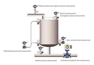
1. Field Symptoms
A differential pressure level transmitter is installed on an industrial reactor for continuous level monitoring.
During operation, the following symptoms are observed:
- The control room level reading fluctuates frequently.
- The local reference level remains relatively stable.
- Signal fluctuations become more noticeable when the agitator is running.
- The signal becomes less unstable after certain equipment is stopped.
2. Fault Analysis
Two main areas should be investigated: process disturbances and the instrument measurement system.
First, agitation inside the reactor may cause liquid surface disturbances and local pressure variations.
If the pressure tapping point is close to the agitation zone or exposed to significant fluid impact, the measurement signal may be affected.
Second, gas accumulation, deposits, or partial blockage inside the impulse lines may cause delayed pressure transmission and unstable readings.
In addition, an excessively low transmitter damping setting may make the output too sensitive to short-term pressure variations.
3. Field Inspection Procedure
Step 1: Observe whether the level fluctuations are synchronized with agitator operation.
Step 2: Inspect the pressure tapping point and determine whether it is exposed to significant fluid disturbance.
Step 3: Check the high- and low-pressure impulse lines for gas accumulation or partial blockage.
Step 4: Inspect the transmitter mounting and mechanical support.
Step 5: Check the power supply, electrical connections, shielding, and grounding.
Step 6: Verify the transmitter damping configuration.
4. Corrective Actions
Depending on the actual inspection results, apply the appropriate corrective measures:
- If the problem is caused by process-induced liquid surface disturbance, evaluate the pressure tapping location and measurement arrangement according to process conditions.
- If gas accumulation is identified, remove the accumulated gas in accordance with the approved procedure.
- If impulse line blockage is confirmed, isolate the system safely before cleaning.
- If electrical interference is identified, inspect grounding, shielding, and cable routing.
- If the damping setting is inappropriate, adjust it according to the required process response time.
5. Engineering Lessons
An unstable level signal does not necessarily indicate transmitter failure.
For stirred tanks and reactors, actual liquid level changes, process pressure disturbances, and instrument measurement faults must be distinguished.
Simply increasing transmitter damping is not an appropriate solution for every fluctuation problem.
Case Study 3: Level Reading Remains Constant Despite Changes in Process Level
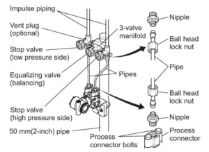
1. Field Symptoms
A differential pressure transmitter is installed on an industrial process tank for continuous level measurement.
During operation, the following conditions are observed:
- Tank filling and discharging operations continue normally.
- The control room level indication remains at a fixed value for an extended period.
- The local level changes, but the transmitter reading shows little or no response.
- The transmitter does not display an obvious electronic fault alarm.
2. Fault Analysis
This condition requires priority inspection of the pressure transmission path.
If either the high-pressure or low-pressure impulse line is completely blocked, process pressure cannot be transmitted correctly to the transmitter.
The transmitter may continue to retain its previous pressure condition, resulting in a fixed or slow-changing level indication.
Other possible causes include:
- A closed pressure tapping valve.
- Incorrect valve manifold operating conditions.
- An equalizing valve that has not been closed.
- Transmitter sensor failure.
- Frozen DCS input signal or incorrect control system configuration.
3. Field Inspection Procedure
- Verify the positions of the high- and low-pressure isolation valves.
- Check the operating condition of the three-valve or five-valve manifold.
- Inspect the pressure tapping points and impulse lines for blockage.
- Use an appropriate calibration device to verify transmitter pressure response under safe conditions.
- Measure the 4-20 mA output signal.
- Compare the local transmitter indication with the DCS reading.
4. Corrective Actions
If impulse line blockage is confirmed, isolate, depressurize, and clean the affected line according to the process medium characteristics, pressure rating, and site safety requirements.
If the transmitter input pressure changes normally but the output signal remains unchanged, inspect the sensor and electronic module.
If the local output signal is normal but the DCS indication remains fixed, focus on the signal wiring, isolator, and DCS input channel.
5. Engineering Lessons
When the actual field level changes but the transmitter reading remains constant, inspect the pressure transmission path and signal transmission path before concluding that the transmitter itself has failed.
This troubleshooting sequence helps reduce unnecessary transmitter replacement and repeated calibration.
5. Systematic Troubleshooting Procedure for Differential Pressure Level Transmitters
In industrial field applications, troubleshooting should follow a structured sequence to avoid unnecessary dismantling or repeated parameter adjustments.
Recommended Diagnostic Sequence
Step 1: Confirm the Actual Process Level
Compare the transmitter reading with a local level gauge, sight glass, or another reliable measurement method to determine whether the process level has actually changed.
Step 2: Check Process and Fluid Parameters
Verify the process fluid density, temperature, pressure, concentration, and operating conditions.
Step 3: Inspect Impulse Lines and Pressure Tapping Points
Check for blockage, leakage, gas accumulation, liquid accumulation, crystallization, and freezing.
Step 4: Inspect the Valve Manifold and Installation Configuration
Verify the high- and low-pressure connections, isolation valves, equalizing valve, and wet-leg or dry-leg conditions.
Step 5: Inspect the Differential Pressure Transmitter
Check the differential pressure input, zero elevation or suppression, measuring range, damping settings, and diagnostic information.
Step 6: Inspect the Signal Transmission System
Check the 24 V DC power supply, 4-20 mA signal, electrical connections, signal isolators, and DCS input.
Step 7: Perform Corrective Maintenance and System Verification
After maintenance, verify the zero point, measuring range, output signal, and response to actual field level changes.
Quick Reference: Common Faults and Inspection Priorities
| Fault Symptom | Priority Inspection Area | Key Diagnostic Direction |
|---|---|---|
| Level reading too high | Impulse lines and wet leg | Hydrostatic head and zero settings |
| Level reading too low | High- and low-pressure sides | Pressure transmission and density changes |
| Frequent level fluctuations | Pressure tapping points and impulse lines | Process disturbances and pressure pulsations |
| Level reading remains fixed | Valve manifold and impulse lines | Blockage or closed valves |
| Delayed level response | Impulse lines and damping settings | Restricted pressure transmission |
| Local reading normal, remote reading abnormal | Electrical loop and DCS | Signal transmission and configuration |
| Continuous zero-point drift | Installation configuration and wet leg | Liquid column changes and installation effects |
6. Maintenance and Calibration Considerations
To reduce the probability of measurement faults, maintenance activities should cover the entire measurement system rather than focusing exclusively on the transmitter.
6.1 Regular Inspection of Impulse Lines
Inspection intervals should be established according to the process fluid characteristics and actual operating conditions.
For fluids prone to crystallization, deposition, polymerization, or containing solid particles, particular attention should be paid to pressure tapping points and impulse lines.
In low-temperature environments, insulation and heat tracing should be checked to prevent impulse line freezing.
6.2 Regular Inspection of Valve Manifolds
Check the sealing condition and operating flexibility of isolation valves and equalizing valves.
Prevent internal leakage, incorrect operation, or abnormal valve positions from affecting differential pressure measurement.
After maintenance, restore the valve configuration according to the manufacturer’s specified operating procedure.
6.3 Correct Zero-Point Calibration
Zero-point calibration must be performed according to the specific installation configuration.
The following points require particular attention:
- Open-vessel and closed-vessel measurement configurations are different.
- Dry-leg and wet-leg installations require different zero-point calculations.
- Remote diaphragm seal systems are affected by capillary fill-fluid hydrostatic pressure.
- Transmitter elevation may affect zero elevation or suppression.
- Zero adjustment must not be performed when the two pressure sides are not in the correct reference condition.
Important Principle: Zero-point calibration should only be performed after the measurement system’s design conditions and correct pressure reference state have been established.
The zero setting must not be adjusted simply to make the display return to zero while an underlying impulse line or installation fault remains unresolved.
6.4 Correct Range Calibration
Before calibration, verify the instrument tag number, design range, process fluid, density, installation configuration, and range migration parameters.
For differential pressure level measurement, 4 mA does not necessarily correspond to zero mmH2O, nor does 20 mA necessarily correspond to a fixed liquid column height.
The actual Lower Range Value (LRV) and Upper Range Value (URV) must be calculated according to the vessel configuration, transmitter elevation, and liquid columns in the impulse lines.
6.5 Monitoring Operating Trends
Historical DCS trends can help identify gradual signal drift, intermittent fluctuations, and abnormal measurement responses.
For critical storage tanks and process vessels, independent measurement methods can be used for cross-verification where appropriate.
This helps reduce the risk of incorrect process decisions caused by a single instrument failure.
7. Safety Requirements During Field Maintenance
Differential pressure level transmitters are normally connected to process vessels and pressure piping. All maintenance activities must strictly comply with the site’s process safety procedures and equipment maintenance requirements.
The following precautions are particularly important:
- Never dismantle pressurized impulse lines without proper isolation and depressurization. Confirm that the system has been safely isolated and depressurized before maintenance.
- Prevent process fluid leakage. Appropriate protective measures must be implemented for high-temperature, high-pressure, flammable, corrosive, and toxic media.
- Operate three-valve and five-valve manifolds correctly. Incorrect operation may cause overpressure on one side, pressure surges, or measurement failure.
- Do not open the equalizing valve indiscriminately. Follow the manufacturer’s procedure and the specific maintenance requirements.
- Prevent unintended interlock activation. Before working on important level measurement loops, obtain the required work permits and approvals in accordance with plant procedures.
- Perform functional verification after calibration. Confirm consistency between the local indication, remote signal, and control system.
For level measurement loops associated with safety instrumented functions or process interlocks, applicable bypass authorization, risk controls, and restoration confirmation procedures must also be followed.
8. Conclusion: Key Principles for Differential Pressure Level Transmitter Troubleshooting
Although differential pressure level transmitters operate according to a relatively straightforward measurement principle, their accuracy is influenced by multiple factors, including process fluid density, pressure conditions, impulse line conditions, installation elevation, and transmitter configuration.
In practical industrial applications, an abnormal level indication should not automatically be attributed to transmitter failure.
The entire measurement system must be evaluated systematically.
The following diagnostic principles are particularly important:
- Incorrect level indication: Focus on process fluid density, liquid column height, and zero elevation or suppression.
- Unstable level readings: Focus on process disturbances, impulse line conditions, and electrical interference.
- Fixed level readings: Inspect pressure tapping points, valve manifolds, impulse lines, and output circuits.
- Continuous measurement drift: Check wet-leg liquid columns, temperature effects, and installation conditions.
- Abnormal remote indication: Focus on the 4-20 mA signal loop and DCS system.
- Calibration problems: Verify the measurement principle, installation configuration, and range calculations.
The key to differential pressure level transmitter troubleshooting is not simply adjusting instrument parameters. It is determining whether pressure transmission, differential pressure conversion, and signal output are functioning correctly.
Only by combining process conditions, instrument configuration, and field inspection results can measurement problems be properly resolved, improving the reliability of industrial instrumentation and the stability of process automation systems.
9. Technical References and Further Reading
The troubleshooting principles discussed in this article are consistent with commonly used industrial differential pressure measurement practices and manufacturer technical documentation.
Recommended reference materials for further engineering study include:
- Emerson Rosemount 2051 Pressure Transmitter Reference Manual – covering transmitter operation, configuration, pressure measurement, diagnostics, and troubleshooting.
- Emerson Rosemount 3051 Pressure Transmitter Reference Manual – covering transmitter setup, calibration, electrical connections, and diagnostic procedures.
- Industrial Differential Pressure Measurement and Impulse Line Installation Guidelines – covering impulse line arrangement, gas and liquid accumulation, hydrostatic head effects, and zero-point verification.
Related pages:
What Is a Pressure Transmitter? Working Principle, Types, Parameters & Selection Guide
Excessive Differential Pressure Across Pipeline Filters or Dryers, but No Pressure Monitoring