Electromagnetic Flow Meter Electrode Fouling: Practical Field Troubleshooting and Cleaning Tips
1. Direct Answer: How Should Electrode Fouling in an Electromagnetic Flow Meter Be Handled?
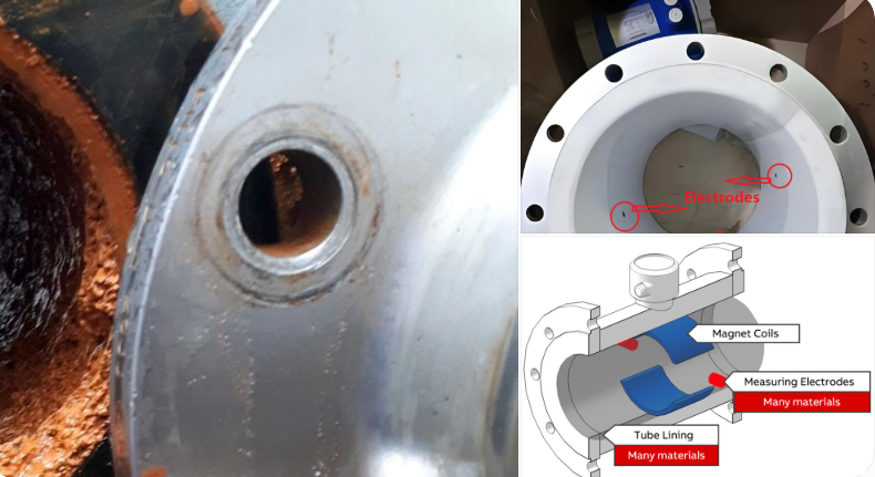
Electrode fouling in an electromagnetic flow meter occurs when minerals, suspended solids, grease, slurry, or chemical deposits accumulate on the electrode surfaces. These deposits can affect the electrical interaction between the electrodes and the conductive liquid, potentially causing unstable readings, abnormal flow indications, or even signal loss.
During field maintenance, do not immediately remove the electrodes or use strong acids or alkalis for cleaning. The correct approach is to identify the type of deposit first, then select a suitable cleaning method based on the process medium, electrode material, and deposit characteristics. Grounding, wiring, and converter signals should also be checked to avoid misdiagnosing an electrical problem as electrode fouling.
For applications prone to electrode fouling, preventive measures should also be considered, including electrode design, installation location, medium pretreatment, and routine maintenance.
2. Key Takeaways: Important Points for Field Maintenance
- Inspect before cleaning: Distinguish electrode fouling from air bubble interference, partially filled pipes, and improper grounding.
- Select the cleaning method according to the deposit: Mineral scale, grease, slurry, and biological deposits require different cleaning approaches.
- Protect the electrode surface: Avoid scraping electrodes with wire brushes, sandpaper, or other abrasive tools.
- Follow proper safety procedures: Confirm the medium properties, pipeline pressure, temperature, and equipment isolation requirements before cleaning.
- Prevent recurring deposits: Optimize installation conditions, medium filtration, and maintenance intervals.
3. Why Do Electromagnetic Flow Meter Electrodes Become Fouled?
An electromagnetic flow meter operates according to Faraday’s law of electromagnetic induction. When a conductive liquid flows through a magnetic field, an induced voltage proportional to the flow velocity is generated. Electrodes installed on opposite sides of the measuring tube detect this small electrical signal.
Therefore, the condition of the electrode surfaces directly affects measurement signal stability.
In industrial applications, electrode fouling is commonly associated with the following conditions.
3.1 Mineral Scale and Deposits
Typical applications: Cooling water systems, boiler feedwater systems, groundwater measurement, and industrial circulating water systems.
When water contains relatively high concentrations of calcium, magnesium, and other dissolved minerals, deposits such as carbonates may form under certain temperature, pressure, and water chemistry conditions. These deposits can gradually accumulate on the electrode surfaces.
Typical field symptoms:
- Flow readings gradually become unstable.
- Measured flow differs from the expected process flow.
- White or yellowish deposits are visible on the electrode surfaces during inspection.
- Measurement signals improve after cleaning but become abnormal again after a period of operation.
3.2 Grease and Viscous Material Deposits
Typical applications: Food processing, oil-water mixtures, wastewater treatment, and chemical wastewater systems.
Grease, gel-like substances, and certain high-viscosity materials can form deposits on electrode surfaces. These deposits are often difficult to remove completely by simply rinsing with water.
Typical field symptoms:
- An oil film or sticky material is visible on the electrodes.
- Residue remains after rinsing with clean water.
- Flow signals become intermittently unstable.
- Thick deposits may gradually develop around the electrodes during long-term operation.
3.3 Sludge and Suspended Solid Accumulation
Typical applications: Municipal wastewater, industrial wastewater, paper mill effluent, and slurry transportation.
When the measured medium contains large amounts of fibers, sludge, particles, or other suspended solids, some of these materials may accumulate around the electrodes.
This problem can become more noticeable when the flow velocity is low, the medium tends to settle, or localized stagnant zones exist within the pipeline.
Typical field symptoms:
- Flow readings occasionally fluctuate.
- Sludge or fibers are visible around the electrodes.
- The meter operates normally for a short period after cleaning, but the problem returns.
3.4 Biological Slime and Microbial Deposits
Typical applications: Long-running circulating water systems, wastewater treatment plants, and cooling tower pipelines.
Under suitable temperature and nutrient conditions, microorganisms may form biofilms on the internal surfaces of pipelines. As operation continues, these biofilms may cover the electrode surfaces and affect the electrical interaction between the electrodes and the liquid.
It is important to understand that not all deposits on electrode surfaces are electrically insulating. Their effects depend on electrical conductivity, deposit coverage, electrode design, and the electrical characteristics of the measuring system.
An insulating deposit may weaken the electrode signal, while conductive deposits may create abnormal electrical paths between electrodes or between an electrode and ground.
4. Practical Field Troubleshooting: Five Ways to Handle Electrode Fouling
This is one of the most important sections for field maintenance personnel. In actual applications, the following troubleshooting sequence is recommended.
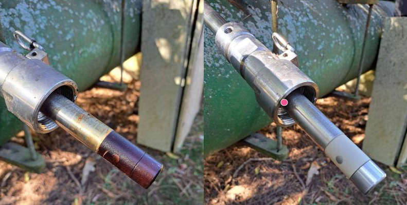
Tip 1: Inspect the Electrode Surface and Identify the Deposit Type
Do not immediately disassemble the instrument whenever abnormal flow readings occur.
First, check the operating conditions and identify the possible deposit type based on the characteristics of the process medium.
| Deposit Type | Typical Appearance | Recommended Approach |
|---|---|---|
| Carbonate scale | White or grayish hard deposits | Select a compatible descaling method after material compatibility assessment |
| Grease deposits | Oily film or yellowish/brown sticky material | Use a compatible degreasing agent |
| Sludge deposits | Black, gray, or brown muddy material | Rinse first, then clean with soft tools |
| Biological slime | Slippery or gel-like deposits | Apply a cleaning and disinfection procedure suitable for the process |
Field Tip: If the meter returns to normal shortly after cleaning but develops the same problem again after a period of operation, investigate the medium composition, flow velocity, and installation location rather than simply increasing the cleaning frequency.
Tip 2: Prioritize Gentle Mechanical Cleaning
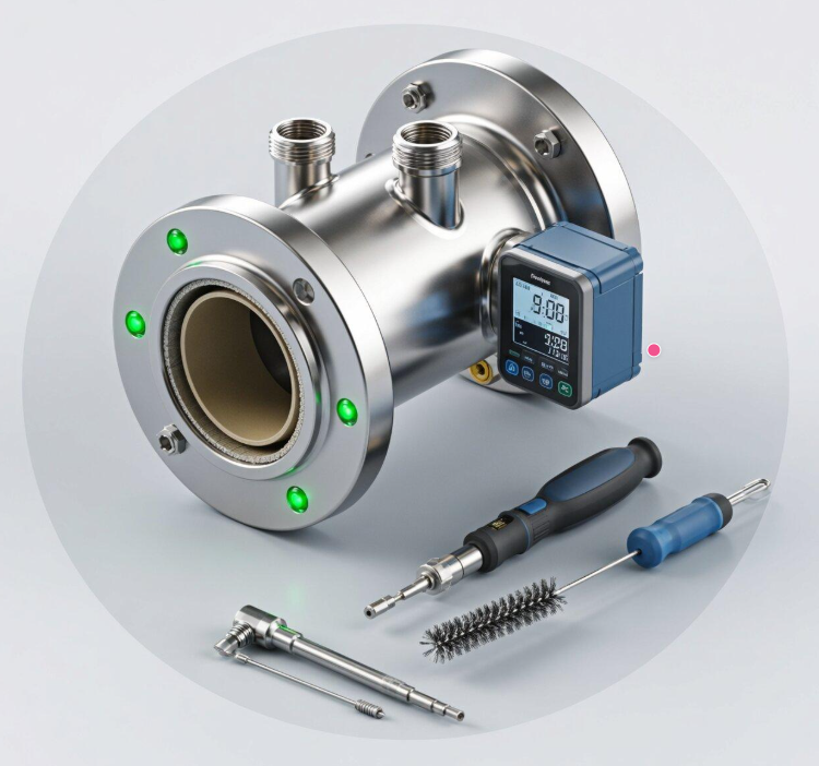
For ordinary sludge, loose deposits, and some soft contaminants, manual cleaning may be suitable after the equipment has been safely isolated.
Recommended procedure:
- Stop the relevant process and close the upstream and downstream isolation valves.
- Depressurize and drain the pipeline according to site safety procedures. Ensure that the medium has been handled safely.
- Remove the sensor or open the inspection point according to the equipment design and manufacturer’s instructions.
- Gently remove deposits using a soft, lint-free cloth, soft-bristle brush, or other compatible cleaning tool.
- Rinse the electrode surfaces with a cleaning solution compatible with the electrode and lining materials.
- Inspect the electrodes for scratches, corrosion, pitting, or abnormal wear.
- Check the seals and connections before reinstalling the equipment according to the manufacturer’s requirements.
Important precautions:
- Do not use wire brushes, sandpaper, or metal scrapers directly on electrode surfaces.
- Do not use strong acids or alkalis without confirming material compatibility.
- Do not direct high-pressure water jets at close range toward the electrodes or measuring tube lining.
- Do not attempt to remove electrodes from non-removable electrode structures.
Electrode materials may include stainless steel, Hastelloy alloys, tantalum, titanium, and other materials. Their chemical resistance varies considerably. Cleaning agents must be selected based on the electrode material, lining material, sealing materials, and actual process medium.
Tip 3: Select the Cleaning Method According to the Deposit Type
One common mistake in field maintenance is using the same cleaning solution for every type of deposit.
Different contaminants require different treatment approaches.
| Deposit Type | Suggested Cleaning Method | Important Considerations |
|---|---|---|
| Ordinary sludge | Rinse with clean water and use a soft-bristle brush | Avoid damaging the electrodes |
| Carbonate scale | Use a suitable descaling agent after confirming material compatibility | Do not apply strong acids directly |
| Grease deposits | Use a compatible neutral or dedicated degreasing agent | Check for cleaning agent residue |
| Biological slime | Mechanical cleaning combined with an appropriate cleaning procedure | Apply disinfection when required by the process |
| Fibers and particles | Flush and remove accumulated materials; inspect upstream filtration conditions | Investigate the cause of recurring accumulation |
An important technical detail:
If the electrodes are made of special materials such as tantalum, do not select a cleaning agent based only on the type of deposit. Chemical compatibility with the electrode, lining, and sealing materials must also be verified.
If the deposit composition is unknown, collect a sample for analysis before deciding on the cleaning procedure.
Tip 4: Do Not Assume the Meter Is Fully Recovered Immediately After Cleaning
In many field situations, maintenance personnel consider the problem solved once the flow reading returns to normal after cleaning.
However, a complete operational check is still necessary.
The following points should be inspected:
- Whether any deposits remain on the electrode surfaces.
- Whether the electrodes show signs of corrosion, damage, or looseness.
- Whether the measuring tube is completely filled with liquid.
- Whether excessive air bubbles are present in the pipeline.
- Whether the grounding rings, grounding cables, and terminal connections are in good condition.
- Whether the flow converter displays any alarm messages.
- Whether the instantaneous flow reading and the 4–20 mA signal received by the PLC are consistent.
Recommended verification method:
Under stable process conditions, with the measuring tube completely filled and the actual flow rate stable, monitor the instantaneous flow reading, output signal, and totalized flow to confirm normal operation.
If a verified reference flow meter or calibration facility is available, a comparative test can be performed.
Please note that zero-point verification should only be carried out when the measuring tube is full of liquid, the medium is stationary, and the manufacturer’s zero-adjustment requirements are satisfied. Do not perform arbitrary zero adjustments when the pipeline is empty.
Tip 5: Consider Online Electrode Cleaning for Applications with Frequent Fouling
If an electromagnetic flow meter is installed in a continuous production line, frequent shutdowns and disassembly for manual cleaning may increase maintenance costs and affect production efficiency.
Depending on the application, the following solutions may be considered.
1. Built-in Electrode Cleaning Function
Some electromagnetic flow meters provide dedicated electrode cleaning functions. These use specific electrical cleaning techniques to reduce deposits on the electrode surfaces.
For example, certain instruments use AC cleaning to address non-conductive deposits such as grease, while DC cleaning is used for certain conductive deposits.
However, these functions are not available on all electromagnetic flow meters. The cleaning principle, suitable deposit types, electrode materials, and operating conditions must be confirmed in the corresponding product manual.
In particular, one electrical cleaning method should not be applied universally to all electrode materials and applications.
2. Select an Appropriate Electrode Design
For applications prone to deposit accumulation, consider suitable electrode structures during the selection stage. Certain electrode designs incorporate protruding structures to improve local flow conditions and reduce deposit accumulation around the electrodes.
The suitability of a particular design must be evaluated based on the medium, flow velocity, pressure, and manufacturer’s specifications.
3. Optimize Pipeline Pretreatment
For media containing large amounts of suspended particles, fibers, and impurities, consider whether suitable filtration or pretreatment equipment should be installed upstream.
Filters should not be selected arbitrarily. Medium properties, particle size, allowable pressure drop, and filter maintenance requirements must all be considered.
5. Common Misdiagnoses: Flow Fluctuations Do Not Always Mean Electrode Fouling
This is an important point during field troubleshooting.
When an electromagnetic flow meter shows unstable readings, flow fluctuations, or measurement deviations, other possible causes should also be investigated.
| Symptom | Possible Cause | Inspection Method |
|---|---|---|
| Sudden fluctuations in flow readings | Electrode deposits or air bubble interference | Inspect the electrodes and process medium |
| Zero flow indication | Empty pipe, insufficient liquid conductivity, or signal failure | Check full-pipe conditions and conductivity |
| Continuously low readings | Electrode coating or actual flow changes | Inspect the electrodes and verify process flow |
| Unstable flow readings | Improper grounding, electromagnetic interference, or air bubbles | Check grounding, shielding, and pipeline conditions |
| Abnormal readings after cleaning | Electrode damage, incorrect wiring, or converter failure | Further inspect the sensor and converter |
Important reminder:
An electromagnetic flow meter requires the measured medium to have sufficient electrical conductivity. The minimum conductivity requirement varies by instrument model. Not all liquids are suitable for electromagnetic flow measurement.
If the local display is normal but the PLC receives an abnormal flow signal, also check the 4–20 mA output loop, wiring, and PLC analog input configuration. Do not immediately classify the problem as electrode failure.
6. How to Prevent Electrode Fouling from Happening Again
Rather than repeatedly removing and cleaning the meter, it is better to consider fouling risks during equipment selection and installation.
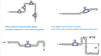
6.1 Choose a Suitable Installation Location
Avoid installing electromagnetic flow meters in locations where deposits are likely to accumulate.
During installation, consider the following:
- Ensure that the measuring tube remains completely full under normal operating conditions.
- Avoid installing the meter at pipeline high points where air can accumulate.
- Select an appropriate horizontal or vertical installation arrangement according to the medium characteristics.
- Avoid locations where sludge is likely to accumulate around the electrodes.
- Minimize flow disturbances caused by pumps, elbows, valves, and other pipeline components.
6.2 Select Electrode Materials Based on the Process Medium
Electrode material selection affects not only corrosion resistance but also the long-term reliability of the instrument.
Common electrode materials include:
- 316L Stainless Steel: Suitable for many conventional industrial water applications and general-purpose media, depending on the chemical composition.
- Hastelloy Alloys: Suitable for certain corrosive process media.
- Titanium: Used for selected special chemical applications.
- Tantalum: Suitable for certain highly corrosive applications, subject to verification of chemical compatibility.
No single electrode material can solve every fouling problem. Selection should consider the medium composition, concentration, temperature, pressure, and corrosive properties.
6.3 Establish a Reasonable Cleaning Schedule
For applications prone to electrode fouling, establish a maintenance plan based on actual operating conditions.
| Maintenance Activity | Recommended Inspection Items |
|---|---|
| Daily inspection | Flow readings, alarm messages, and output signals |
| Periodic inspection | Grounding connections, terminal wiring, and operating conditions |
| Shutdown maintenance | Electrode surfaces, measuring tube interior, and lining condition |
| After cleaning | Measurement signals, zero-point condition, and output loop |
| Long-term operating review | Fouling rate, cleaning frequency, and changes in medium properties |
There is no need to prescribe a fixed cleaning interval, such as monthly or quarterly, for every installation.
A meter measuring clean water may operate for a long time without requiring cleaning, while applications involving high-concentration sludge or crystallizing media may require more frequent inspection.
The actual maintenance interval should be determined according to deposit accumulation rates and historical maintenance records.
6.4 Optimize Pipeline Flow Velocity When Necessary
Low flow velocity may increase the risk of particle settlement in certain measuring tube applications.
However, higher flow velocity is not always better.
For slurry containing hard particles, excessive flow velocity may accelerate wear on the electrodes and measuring tube lining. Therefore, flow velocity should be evaluated based on the medium characteristics, pipe diameter, particle concentration, and the allowable operating range specified by the manufacturer.
Some manufacturers recommend increasing flow velocity for specific electrode fouling conditions. However, this recommendation should not be applied universally to all wastewater and slurry applications.
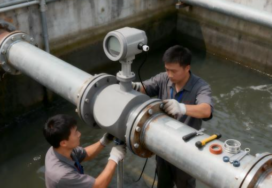
7. Realistic Application Scenario: How to Handle Electrode Fouling in a Wastewater Treatment Plant
The following example illustrates a typical field maintenance situation.
Operating Conditions:
An electromagnetic flow meter is installed in an industrial wastewater treatment system to measure wastewater flow.
When first commissioned, the meter provides stable readings. After a period of operation, however, the local display begins to fluctuate intermittently, and the measured value differs from the expected process flow.
Step 1: Check Operating Conditions
Maintenance personnel first check whether the pipeline is completely full, whether the pump is operating steadily, and whether excessive air bubbles are present in the medium.
Step 2: Inspect the Electrode Surfaces
After isolating the pipeline, releasing pressure, and completing the required safety procedures, the maintenance team inspects the electrodes and finds considerable sludge and sticky deposits on their surfaces.
Step 3: Clean the Electrodes
The deposits are removed using a cleaning method compatible with the electrode materials. The electrodes are also inspected for corrosion and physical damage.
Step 4: Restore Operation and Verify Performance
After reinstallation, the team confirms that the measuring tube is full and checks the instrument grounding, signal connections, and converter output.
The flow readings are then monitored under stable process conditions.
Step 5: Improve Future Maintenance
To address recurring sludge accumulation, the team further evaluates upstream pretreatment, pipeline flow velocity, and instrument installation location, then establishes an inspection schedule based on the actual fouling rate.
Key Field Maintenance Lesson:
Electrode cleaning is only one part of the solution. Without investigating the source of sludge, changes in the process medium, and pipeline operating conditions, the same problem may quickly return even if the meter operates normally immediately after cleaning.
Note: This is an illustrative troubleshooting scenario based on typical industrial operating conditions, not a report of a specific customer’s field test.
8. FAQ: Frequently Asked Questions About Electromagnetic Flow Meter Electrode Fouling
Q1: Does electrode fouling affect the measurement accuracy of an electromagnetic flow meter?
Yes. Deposits on electrode surfaces may change the electrical characteristics between the electrodes and the conductive medium, potentially causing signal interference, measurement deviations, or unstable readings.
The actual impact depends on the electrical conductivity of the deposits, the degree of electrode coverage, and the instrument design.
Q2: Can dilute hydrochloric acid be used directly to clean electromagnetic flow meter electrodes?
This is not recommended without prior compatibility verification.
Although certain carbonate scales can be removed using acidic cleaning solutions, compatibility with the electrode, lining, sealing materials, and other wetted components must first be confirmed.
The cleaning procedure must also comply with the safety requirements of the cleaning agent and instrument manufacturer.
Q3: How often should electromagnetic flow meter electrodes be cleaned?
There is no fixed cleaning interval suitable for every application.
The inspection and cleaning schedule should be determined according to the medium type, deposit accumulation rate, operating hours, and historical maintenance records.
Q4: Will an electromagnetic flow meter always indicate zero flow when its electrodes become fouled?
No. Minor fouling may cause signal fluctuations or measurement deviations. Severe deposits may result in abnormal signals or electrode-related alarms, depending on the instrument’s diagnostic functions and design.
Q5: Are there electrode cleaning methods that do not require manual disassembly?
Yes. Some electromagnetic flow meters provide electronic electrode cleaning functions. Appropriate online cleaning solutions may also be considered for specific applications.
However, not all models support these functions. Their availability and suitability should be confirmed during the instrument selection stage.
Q6: What should be checked if the flow reading remains unstable after electrode cleaning?
Check the following items in sequence:
- Full-pipe conditions.
- Medium electrical conductivity.
- Air bubbles.
- Grounding.
- Shielded cables.
- Signal wiring.
- Converter operating status.
If the local display and PLC signal do not match, also inspect the analog output loop.
9. Conclusion: Clean Electrodes Are Essential for Reliable Electromagnetic Flow Measurement
Electrode fouling is an important maintenance issue in industrial water treatment, wastewater transportation, chemical production, and circulating water systems.
For field engineers, solving electrode fouling problems requires more than simply cleaning the electrodes. It is equally important to identify the cause of the deposits, understand the characteristics of the process medium, select a cleaning method compatible with the electrode materials, and reduce recurring fouling through proper installation, medium pretreatment, and routine maintenance.
The recommended troubleshooting sequence is:
- Identify abnormal flow readings.
- Check process conditions and electrode surfaces.
- Determine the deposit type and material compatibility.
- Select an appropriate cleaning method.
- Restore operation, verify signals, and optimize the maintenance schedule.
For industrial flow measurement systems, proper instrument selection, correct installation, and systematic maintenance are essential to maintaining long-term measurement reliability.