
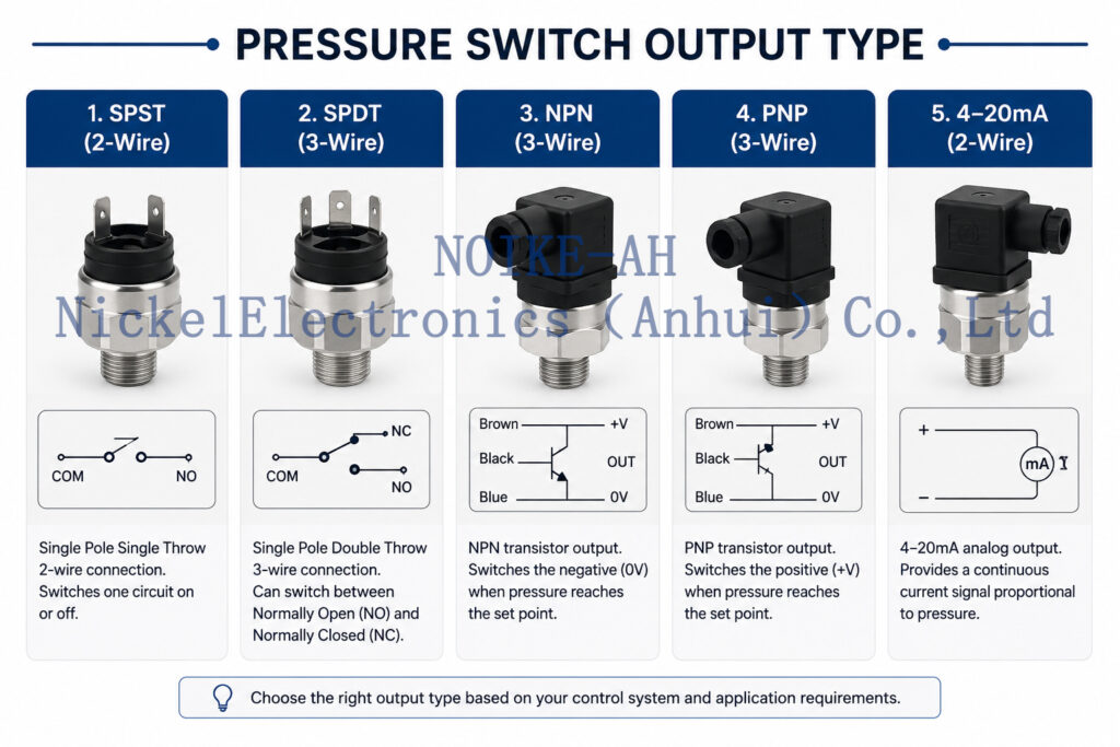
Pressure Switch Output Type
1. Core Diagnosis: The Circuit Mismatch Blind Spot
In pump control panels, booster pump systems, hydraulic power units, cooling water circulation loops, and dry-run protection circuits, pressure switches act as critical binary safety interlocks. They are responsible for low-pressure alarms, high-pressure alarms, pump automated start/stop sequences, and hardware-level safety interlocks.
However, over 85% of field commissioning failures where a “pressure switch fails to trigger the PLC” are not caused by a defective sensor. Instead, they stem from a fundamental electrical mismatch between the pressure switch output stage topology and the PLC Digital Input (DI) module configuration.
The Sinking/Sourcing Rule (AutomationDirect Principle)
Transistor-based switching relies on a strict closed-loop current path:
- PNP Sensors act as current sourcing devices. When triggered, they switch the positive side of the circuit, sending a $+24\text{VDC}$ signal to the PLC. They must be connected to a sinking PLC input (where the PLC input common terminal $\text{COM} = 0\text{V}$).
- NPN Sensors act as current sinking devices. When triggered, they switch the negative side of the circuit, pulling the signal line down to $0\text{V}$. They must be connected to a sourcing PLC input (where the PLC input common terminal $\text{COM} = +24\text{V}$).
If a PNP sensor is mistakenly wired into a sourcing-only control cabinet ($\text{COM} = +24\text{V}$), no electrical current loop can form. The PLC DI channel remains completely blind to the physical state of the pressure switch.
2. Deep Technical Breakdown of Pressure Switch Output Topologies
                       [Determine Pressure Switch Output Topology]
                                           │
         ┌─────────────────────────────────┼─────────────────────────────────┐
         ▼                                 ▼                                 ▼
【Passive Isolated Contacts】     【Transistor: Pulls to 0V】       【Transistor: Supplies +24V】
         │                                 │                                 │
         ▼                                 ▼                                 ▼
  Mechanical / Relay Out                 NPN Output (Sinking)             PNP Output (Sourcing)
• COM / NO / NC terminals           • Switches the negative side     • Switches the positive side
• Requires external loop power      • Matches PLC COM = +24V         • Matches PLC COM = 0V
Pressure Switch Output vs. PLC DI Compatibility Matrix
| Output Stage Type | Output Signal State When Active | Required PLC DI Type | Cabinet Common (COM) Wiring | Typical Field Engineering Error |
| Mechanical Contact (Dry Contact) | Volt-free physical continuity (open/close). | Highly compatible (AC or DC). | Provided by external cabinet loop. | Forgetting to loop $24\text{V}$ into the contact; the circuit closes but no current flows to the DI. |
| Relay Output | Electronically driven isolated dry contact. | Highly compatible; supports cross-voltages. | Flexible; allows isolation between grounds. | Exceeding the contact inductive load rating, leading to premature arc pitting or contact welding. |
| NPN Transistor (Sinking) | Internal solid-state switch pulls down to $\mathbf{0V}$. | Sourcing Input | Must be tied to $\mathbf{+24VDC}$ | Treating the solid-state transistor as a dry contact and wiring it directly into an $\text{AC220V}$ loop, instantly blowing the sensor. |
| PNP Transistor (Sourcing) | Internal solid-state switch supplies $\mathbf{+24V}$. | Sinking Input | Must be tied to $\mathbf{0VDC}$ | Connecting it to a legacy Asian/Japanese style sourcing DI block, causing the signal to stay permanently ON or dead. |
3. Critical Field Failure Modes (Typical Symptoms)
- LED Active but PLC Blind: The intelligent pressure switch local display or LED indicates the setpoint has been reached, and
OUT1is active, but the PLC DI status bit remains zero. This indicates a hard polarity mismatch or mismatched common references. - The Constant-ON Lockout: The PLC input channel remains permanently energized regardless of the physical line pressure. This is often caused by an inverted parameters setting ($\text{Normally Closed}$ vs. $\text{Normally Open}$), back-feeding via a shared common, or a welded physical relay contact.
- Blown Fuses & Fried Channels: The moment the pressure switch activates, the cabinet $\text{24VDC}$ control circuit fuse trips or the PLC input card burns out. This happens when a transistor output is cross-wired directly to the opposite voltage plane without an inline load resistor or DI internal impedance to drop the voltage.
- Interlock Defeat (High Risk): During a suction-side dry-run event, the pressure switch opens mechanically, but due to incorrect wiring topology, the VFD/PLC never processes the stop signal. The pump continues running dry, leading to rapid mechanical seal, bearing, or impeller destruction.
4. Standardized Field Troubleshooting Sequence
When a pressure switch failure is suspected, engineers must systematically test the loop using the following step-by-step verification sequence before condemning the hardware:
[System Interlock/DI Failure]
   │
   ├──► Step 1: Verify Hardware Specs ────► Check Nameplate: Is it Mechanical, Relay, NPN, PNP, or IO-Link?
   │
   ├──► Step 2: Identify PLC Input Polarity ─► Measure voltage at PLC COM terminal:
   │                                           ├───► COM = 0V   ───► Sinking Input (Requires PNP)
   │                                           └───► COM = 24V  ───► Sourcing Input (Requires NPN)
   │
   ├──► Step 3: Multimeter Volt Testing ──► Measure voltage between Black (OUT) and Blue (0V):
   │                                           ├───► Switches 0V to 24V ───► PNP Confirmed
   │                                           └───► Stays at 0V (pulls down) ─► NPN Confirmed
   │
   ├──► Step 4: Logic Configuration Audit ─► Review NO/NC software state. Ensure Fail-Safe NC logic
   │                                        is paired correctly with PLC ladder inversion settings.
   │
   └──► Step 5: Implement Interposing Relay ─► If polarity cannot be matched directly, install a 24VDC
                                             interface relay to adapt the signal safely.
5. NOIKE-AH Industrial Process Control Solutions
As an established manufacturer of industrial sensors and process instrumentation, NOIKE-AH provides a robust suite of solutions spanning fluid flow, pressure, temperature, level, and secondary digital displays. For control panel builders designing mission-critical automated pump skids, the NOIKE-AH Pressure Series delivers seamless electrical compatibility:
NOIKE-AH Electrical Interface Matching Matrix
| Control Cabinet Input Spec | Recommended NOIKE-AH Hardware Solution | Engineering Advantage & Field Value |
| Standard PLC Panels (Sinking Loop, $\text{COM}=0\text{V}$) | NOIKE-AH Intelligent Pressure Switch (PNP Transistor Output) | High-speed solid-state switching, programmable dual-setpoints via local digital display, and built-in short-circuit protection. |
| Legacy / Japanese Style PLC Panels ($\text{COM}=+24\text{V}$) | NOIKE-AH Intelligent Pressure Switch (NPN Sinking Output) | Provides crisp, noise-free grounding paths for sourcing digital inputs, preventing floating signal states. |
| Hardwired Interlock / AC Relays / High Load Circuits | NOIKE-AH Integrated Relay Output Pressure Switch | Built-in isolated form-C contacts ($\text{COM/NO/NC}$) to directly drive heavy contactor coils without an extra panel relay. |
| Outdoor / Explosive / Volt-Free Loops | NOIKE-AH Mechanical Diaphragm Pressure Switch | Pure passive dry-contact configuration. Heavy-duty micro-switch construction requiring zero active power supply. |
| Continuous Process Optimization | NOIKE-AH $4\sim20\text{mA}$ Pressure Transmitter | Delivers linear analog data for precise continuous VFD PID variable speed regulation (not to be mixed with binary switches). |
6. Conclusion & Ordering Specification Standards
Panel builders must move past selecting pressure switches solely by pressure range and thread dimensions. To avoid wiring faults, burnt I/O cards, and system failures, the complete electrical interface must be engineered from day one.
When creating a Bill of Materials (BOM) or cabinet schematic, replace generic descriptors like “Pressure Switch, 0-10 bar” with standardized engineering specifications:
- Standard Specification Example 1:
NOIKE-AH Intelligent Pressure Switch, Range: 0–10 bar g, Output: PNP NO Transistor, Power: 24VDC, M12 4-pin connection, for High Discharge Pressure Interlock. - Standard Specification Example 2:
NOIKE-AH Mechanical Pressure Switch, Range: 1–6 bar, Output: Passive SPDT Relay Contact (COM/NO/NC), for Suction Dry-Run Hardwired Protection.
By executing the Transmitter/Switch Specification Sequence ($\text{Application} \rightarrow \text{Target Interface} \rightarrow \text{Output Polarity} \rightarrow \text{PLC Common Alignment}$), panel builders ensure first-time commissioning success, absolute safety loop integrity, and long-term hardware reliability.



