
Pressure Switch
In pump control panels, booster pump systems, hydraulic power units (HPUs), and cooling water circulation loops, pressure switch logic mismatch (NO/NC inversion) is one of the most common field commissioning issues. This guide deep-dives into the “three-layer logic” of pressure switches, outlines a standard 10-step field troubleshooting procedure, and demonstrates how to build a reliable, compliant Fail-Safe protection system using NOIKE-AH industrial instrumentation.
1. Core Pain Points: Typical Symptoms of NO / NC Logic Mismatch
When the physical pressure switch functions perfectly but the PLC program interprets the NO / NC (Normally Open / Normally Closed) logic incorrectly, the control system exhibits the following faulty symptoms:
- False Alarms: Process pressure is completely normal, but the HMI (Human-Machine Interface) constantly triggers a low-pressure or high-pressure alarm.
- Interlock Failure: Dangerous low-pressure occurs, but the pump fails to trip; or high-pressure occurs, but the safety interlock does not activate.
- Startup Blocked: All process conditions are met, but the “Pump Start Permissive” signal remains inactive.
- Wire-Break Blind Spot: If a control wire breaks or a plug loosens, the system fails to detect the open circuit and assumes conditions are safe.
- Reversed Logic After Replacement: Replacing a mechanical switch or upgrading to an intelligent pressure switch (without configuring the OUT1 digital output) completely reverses the alarm logic.
WIKA Engineering Standard Definition:
NO (Normally Open) and NC (Normally Closed) define the physical contact state of an electrical circuit under zero-force conditions (or below the setpoint). They represent hardware terminal status, not the final PLC internal alarm logic.
2. Key Concept: The “Three-Layer Architecture” of Switch Logic
To eliminate logic mismatch entirely, automation engineers must decouple the signal transmission into three distinct layers:
| Layer | Definition & Meaning | Field Representation |
| Layer 1: Physical Contact | The physical hardware terminal routing. | COM-NO or COM-NC terminal wiring. |
| Layer 2: PLC Digital Input (DI) | The voltage/current status mapped to the PLC input image register. | DI Status is ON (High/24V) or OFF (Low/0V). |
| Layer 3: Program Logic | The process meaning assigned to the DI bit by the ladder logic/code. | Determines if ON/OFF signifies Normal, Alarm, Permissive, or Trip. |
💡 Typical Fail-Safe Design Case: Low Suction Pressure Protection
To protect a centrifugal pump from dry-running, it is highly recommended to wire the pressure switch using the NC (Normally Closed) terminal and program it with the following fail-safe logic:
- Normal Pressure: Contact is Closed $\rightarrow$ PLC DI is ON $\rightarrow$ Program evaluates: Pressure OK.
- Low Pressure (Fault): Contact Opens $\rightarrow$ PLC DI is OFF $\rightarrow$ Program evaluates: Low Pressure Fault (Trip Pump).
- Wire Break / Power Loss: Contact acts as Open $\rightarrow$ PLC DI is OFF $\rightarrow$ Program evaluates: Fault (Safe State Achieved).
3. Field Troubleshooting Procedure: Standard 10-Step Sequence
When the HMI status contradicts the actual line pressure or a safety trip fails to execute, follow this rigorous 10-step field troubleshooting procedure:
- Define the Normal Process State: Confirm the actual current line pressure of the process (Normal, Overpressure, or Depressurized).
- Confirm the Physical Contact Type: Review the pressure switch datasheet or nameplate to check whether wiring is landed on the NO or NC terminal.
- Multimeter Hardware Test: Disconnect the PLC wiring and measure the continuity of the COM-NO/NC contacts under both pressurized and depressurized states.
- Verify Real PLC DI Status: Check the live online value (0 or 1) of the corresponding DI channel in the PLC Watch Table.
- Define DI Logic Meaning: Explicitly clarify whether the design dictates DI ON to mean “Normal” or “Fault”.
- Review Ladder Inversion Logic: Inspect the PLC ladder diagram for any incorrect use or double-negation of Normally Open (
--| |--) and Normally Closed (--|/|--) instructions. - Check Internal Bit Mapping: Trace how the DI status maps to internal variables such as Alarm, Permissive, and Trip bits.
- Validate HMI Text Mapping: Verify if the graphic animations or text lists on the touchscreen are mapped to the wrong bit state.
- Test Wire-Break Behavior: Intentionally disconnect the wire from the pressure switch terminal to verify if the system defaults to a safe shutdown mode.
- Confirm Timers and Bypasses: Verify that the alarm latching, manual reset, startup bypass delay timers, and DI debounce filters are operating as designed.
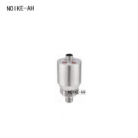
4. Industrial Application: Pressure Monitoring Matrix with NOIKE-AH Instruments
For booster pumps, hydraulic power units, industrial filtration, and cooling water loops, it is recommended to combine NOIKE-AH industrial sensors and digital gauges to construct a hardware-software cohesive pressure protection system.
🛠️ NOIKE-AH Recommended Pressure Protection Configurations
| Function | Recommended Solution | Logic Design Specification |
| Low Suction / Dry-Run Protection | NOIKE-AH Mechanical or Intelligent Pressure Switch | Utilize NC physical contacts to establish absolute Fail-Safe wire-break monitoring. |
| High Pressure Protection | NOIKE-AH Pressure Switch / Controller | Implement NO for alarm-only, or NC to directly break the hardwired safety loop (Trip). |
| Continuous Feedback & PID Control | NOIKE-AH Pressure Transmitter | Utilizes a $4 \sim 20\text{mA}$ analog signal; enables the PLC to execute trend logging and sensor fault diagnostics ($<3.6\text{mA}$). |
| Local Indication | NOIKE-AH Digital Pressure Gauge | Provides high-precision local LED/LCD readouts for easy operators’ visual inspection and field calibration. |
| Critical Safety Interlock | NOIKE-AH Relay Output / Dry Contacts | Hardwires dry contacts directly into the motor starter circuit, ensuring hardware-level tripping independent of the PLC. |
| Commissioning & Sign-Off | DI Normal/Fault Logic Matrix | Compile a complete truth table matching physical states to PLC bits before final sign-off. |
5. Conclusion & Golden Design Rule
A pressure switch NO / NC mismatch is never just a simple wiring mistake. It is a multi-layer control system issue involving physical hardware, PLC configuration, HMI text compilation, and Failure Mode and Effects Analysis (FMEA).
💡 The Golden Rule of Automation Design:
Always define the normal process DI state first, then design the physical wiring and PLC ladder instructions around that baseline.
For all critical safety interlocks, the architecture must ensure that low pressure, overpressure, wire breaks, and power losses automatically guide the system into a predictable, deterministic Fail-Safe shutdown condition.



