Flow Meter vs Flow Switch: What’s the Difference?
Direct Answer
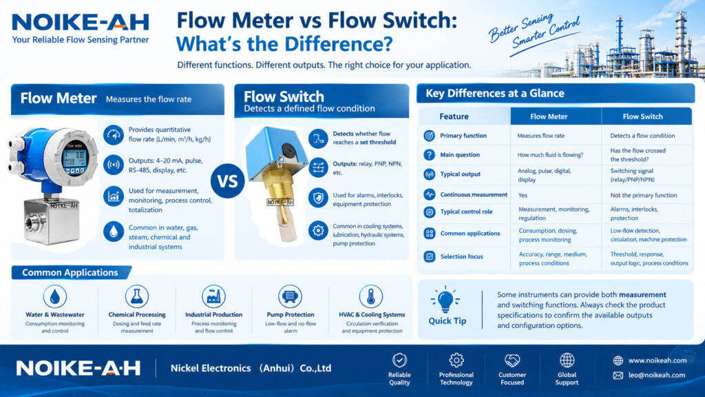
The main difference between a flow meter and a flow switch is their primary function. A flow meter measures the flow rate of a liquid, gas, or steam, while a flow switch detects whether the flow has reached a predefined threshold and generates a switching signal.
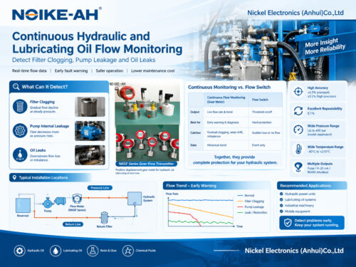
Flow meters are typically used for continuous measurement, process monitoring, consumption tracking, and flow control. Flow switches are commonly used for equipment protection, low-flow alarms, and interlock control in systems such as cooling circuits, lubrication lines, and hydraulic equipment.
The correct choice depends on whether the application requires quantitative flow measurement or reliable detection of a specific flow condition. Some electronic instruments combine both functions, so the required output and operating principle should be verified against the manufacturer’s specifications.
Key Takeaways
- Flow meter: Measures and reports a quantitative flow rate, such as L/min, m³/h, or kg/h, depending on the instrument.
- Flow switch: Detects whether flow is above or below a configured threshold and changes its switching output accordingly.
- Output signals: Flow meters commonly provide display, analog, pulse, or digital communication outputs. Flow switches commonly use relay, PNP, or NPN switching outputs.
- Typical applications: Flow meters support measurement and process control, while flow switches support alarms, equipment protection, and interlocks.
- Selection criteria: Medium, flow range, pressure, temperature, pipe size, installation conditions, and control requirements must all be considered.
1. What Is a Flow Meter?
A flow meter is an industrial instrument designed to measure the rate at which a fluid moves through a pipeline or process system. Depending on the measuring principle, it can measure volumetric flow rate, mass flow rate, or fluid velocity.
The measured value may be displayed locally or transmitted to a programmable logic controller (PLC), distributed control system (DCS), supervisory control and data acquisition (SCADA) system, or other monitoring equipment.
For example, an operator may need to know whether a cooling-water line is delivering 12 m³/h or whether a dosing system is supplying 250 mL/min. A suitable flow meter provides quantitative measurement data for evaluating these conditions.
For a more detailed explanation, see What Is a Flow Meter and How Does It Work?.
How Does a Flow Meter Work?
A flow meter uses a measuring principle suited to the process medium and required measurement range. Common technologies include:
1. Electromagnetic flow meters
Electromagnetic flow meters use Faraday’s law of electromagnetic induction to measure the velocity of electrically conductive liquids. The measured velocity is used to determine volumetric flow rate.
They are commonly considered for conductive liquids such as water, wastewater, and certain chemical solutions. The liquid must have sufficient electrical conductivity, and the liner and electrode materials must be compatible with the medium.
2. Vortex flow meters
Vortex flow meters detect vortices generated downstream of a bluff body in the flow stream. Within the instrument’s applicable operating range, the vortex-shedding frequency is related to fluid velocity.
They are used in suitable liquid, gas, and steam applications, subject to the instrument’s design and operating limits.
3. Positive displacement flow meters
Positive displacement flow meters measure fluid by repeatedly capturing and passing defined volumes through a measuring chamber. They can be suitable for applications involving clean liquids, including certain viscous fluids.
4. Ultrasonic flow meters
Ultrasonic flow meters use acoustic signals to determine fluid velocity or flow rate. Depending on the design, they may be installed externally on the pipe or directly in contact with the fluid.
The suitability of each technology depends on the medium, flow range, pipe configuration, and measurement requirements.
For additional guidance, read How to Choose an Industrial Flow Meter: Complete Selection Guide.
Typical Applications of Flow Meters
Flow meters are commonly used when a process requires a numerical flow-rate value or accumulated quantity.
Examples include:
- Measuring water consumption in industrial production.
- Monitoring chemical feed rates in process systems.
- Measuring fuel, oil, or other suitable liquids.
- Monitoring compressed air or gas consumption.
- Measuring steam flow for process monitoring or energy management.
- Controlling flow rates in automated production lines.
- Measuring liquid quantities in batching and dosing systems.
A flow meter is generally the appropriate choice when operators need to know not only whether fluid is moving, but also how much fluid is passing through the system.
2. What Is a Flow Switch?
A flow switch is a device that detects a specified flow condition and changes its output state when the measured condition crosses a configured switching threshold.
Instead of primarily reporting an exact flow rate, a conventional flow switch answers a practical question:
Is the flow sufficient for the equipment or process to operate safely?
For example, a cooling system may require confirmation that coolant is flowing before a machine is allowed to operate. If the flow falls below the required threshold, the switch can send a signal to an alarm system or PLC.
The receiving control system can then initiate an alarm, stop equipment, or execute another configured action. The final response depends on the control logic and safety design; the switch itself does not automatically guarantee equipment protection.
How Does a Flow Switch Work?
Flow switches use different sensing technologies. The appropriate working principle depends on the medium and operating conditions.
1. Mechanical flow switches
Mechanical designs may use a paddle, piston, target, or another moving element that responds to fluid movement. When the force generated by the flow reaches a defined level, the mechanism changes the switch state.
Mechanical flow switches can be suitable for certain water, oil, and industrial circulation applications. Their suitability depends on viscosity, pressure, flow conditions, mechanical design, and the possibility of deposits or moving-part wear.
2. Thermal dispersion flow switches
Thermal flow switches use heat transfer between a heated sensing element and the surrounding fluid. As fluid moves past the probe, it changes the amount of heat removed from the sensing element. The electronics evaluate this thermal response and compare it with a configured switching threshold.
These devices can be useful for flow/no-flow and low-flow detection in suitable liquid and gas applications. Their response depends on the medium’s thermal properties, operating temperature, sensor condition, and calibration.
Unlike mechanical designs, thermal dispersion switches have no moving parts in the sensing element.
3. Other electronic flow switches
Other designs may use different sensing principles, including electromagnetic, ultrasonic, or turbine-based sensing elements combined with switching electronics. The available technologies and outputs depend on the product.
For a more detailed technical explanation, read Thermal Flow Switch Principle & Applications.
Typical Applications of Flow Switches
Flow switches are commonly used where a flow condition must trigger an alarm or control action.
Typical examples include:
- Detecting insufficient cooling-water flow in industrial equipment.
- Monitoring lubrication flow to bearings or rotating machinery.
- Providing low-flow alarms in hydraulic systems.
- Supporting pump protection when loss of flow is a relevant fault condition.
- Verifying circulation in suitable heat exchangers and cooling circuits.
- Providing flow-status signals to PLCs and industrial control systems.
For example, a flow switch installed in a lubrication line can help identify a flow condition below its configured threshold. The control system can use that signal to initiate an alarm or shutdown sequence if the application requires it.
For pump protection, however, flow detection should be evaluated alongside the pump design, process conditions, and other protection measures. A flow switch alone may not detect every dry-running condition.
See also Pump Dry-Run Protection: Flow Switch vs. Level Switch vs. Current Monitoring.
3. Flow Meter vs Flow Switch: Key Differences
The following table summarizes the main differences between the two instruments.
| Comparison | Flow Meter | Flow Switch |
|---|---|---|
| Primary function | Measures flow rate | Detects a defined flow condition |
| Main question | How much fluid is flowing? | Has the flow crossed the switching threshold? |
| Typical output | Flow-rate value, analog signal, pulse, or digital data | Discrete switching signal |
| Common electrical interfaces | 4–20 mA, pulse, RS-485 or other supported interfaces | Relay, PNP, NPN or other supported switching interfaces |
| Local indication | Available on many models | Depends on the model; some provide LED or numerical indication |
| Continuous flow-rate measurement | Yes, within the specified operating range | Not the primary function of a conventional flow switch |
| Typical control role | Measurement, monitoring, regulation, and totalization | Alarms, interlocks, and equipment protection |
| Common applications | Consumption monitoring, dosing, process measurement | Low-flow detection, circulation verification, machine protection |
| Selection focus | Accuracy, range, measuring principle, and process conditions | Switching threshold, response, output logic, and process conditions |
Important engineering note: These categories are not mutually exclusive at the hardware level. Some flow meters include alarm outputs, and some electronic flow sensors provide both switching and continuous analog signals. The distinction is the instrument’s measurement function and the signals it is configured to provide, not simply whether it has an electronic output.
4. Flow Meter vs Flow Switch: Which One Should You Choose?
The simplest way to select the correct instrument is to begin with the process objective.
Choose a Flow Meter When You Need Continuous Measurement
A flow meter is generally appropriate when the process requires a numerical measurement of flow rate or accumulated fluid quantity.
Choose this instrument category when you need to:
- Display the actual flow rate during operation.
- Record fluid consumption for production or energy analysis.
- Monitor changes in process flow over time.
- Regulate flow using a PLC, control valve, or variable-frequency drive.
- Measure a specified liquid quantity during a dosing or batching operation.
For example, if a chemical dosing system must deliver a specified quantity of liquid, a suitable flow meter can provide measurement data for the dosing control system. The meter’s accuracy, response, usable flow range, and compatibility with the liquid must be verified for the application.
When selecting a meter for a small flow rate, review How to Choose a Flow Meter for Low-Flow Applications.
Choose a Flow Switch When You Need Threshold-Based Detection
A flow switch is generally appropriate when the control system only needs to know whether flow has reached a defined condition.
Choose this instrument category when you need to:
- Detect flow loss in a cooling circuit.
- Generate a low-flow alarm.
- Verify circulation before allowing equipment to start.
- Trigger a control action when the flow falls below a specified threshold.
- Provide a discrete flow-status input to a PLC.
For example, a machine may require cooling-water flow above a defined minimum before operation. A properly selected flow switch can monitor this condition and provide a switching signal to the control system.
The switching threshold must be selected and verified against the actual process requirements. A flow switch should not be assumed to provide an exact flow-rate reading unless the specific instrument is designed and specified to do so.
What If You Need Both Functions?
Some applications require continuous flow measurement and threshold-based alarms.
In this case, consider a flow meter with suitable configurable alarm outputs or an appropriate combination of a flow meter and a separate flow switch.
The choice depends on the required measurement accuracy, response time, control-system architecture, redundancy requirements, and consequences of flow loss.
Before ordering, confirm that the instrument supports the required signal types and that its alarm or switching behavior can be configured for the application.
5. Key Parameters to Check Before Selection
Whether you choose a flow meter or a flow switch, the instrument must be suitable for the actual process conditions.
1. Fluid Medium
Identify whether the medium is a liquid, gas, or steam. For liquids, determine whether it is conductive, viscous, corrosive, clean, or contains suspended solids.
These properties influence the suitable measuring principle and wetted materials.
For corrosive liquids, consult How to Choose a Flow Meter for Corrosive Liquids: A Practical Selection Guide.
2. Minimum, Normal, and Maximum Flow
Provide the complete operating range rather than only the nominal or maximum flow rate.
For a flow meter, verify that the required range falls within the instrument’s specified measurement range and that the required accuracy can be achieved throughout the relevant operating conditions.
For a flow switch, establish the minimum acceptable flow and the required switching threshold. Confirm that the instrument can detect the target condition reliably.
3. Operating Pressure and Temperature
Check the normal operating conditions as well as foreseeable pressure and temperature variations.
The sensor body, seals, process connections, and wetted components must be rated for the intended application.
4. Pipe Size and Installation
Confirm the pipe diameter, connection type, installation orientation, and available straight pipe sections where relevant.
Some flow meters require particular upstream and downstream installation conditions to achieve their specified performance. Flow switches also require correct positioning to detect the intended flow condition.
Follow the installation instructions for the specific instrument.
5. Output Signal and Control Requirements
Determine how the instrument will communicate with the control system.
For a flow meter, possible requirements include:
- 4–20 mA for continuous flow-rate transmission.
- Pulse or frequency output for suitable measurement and totalization tasks.
- Digital communication such as RS-485, when supported.
For a flow switch, determine whether the application requires a relay, PNP, NPN, or another supported output.
Check electrical ratings, supply voltage, PLC input compatibility, and the desired signal state during normal and fault conditions.
6. Maintenance and Operating Environment
Consider deposits, vibration, contamination, mechanical wear, and access for inspection.
Thermal flow switches may require special attention to sensor coating and medium-dependent thermal behavior. Mechanical switches may require inspection for sticking or wear. Flow meters have their own technology-specific maintenance requirements.
Selection should account for the complete operating environment rather than relying on the device category alone.
6. Common Selection Mistakes
Mistake 1: Expecting a Flow Switch to Display an Exact Flow Rate
A conventional flow switch indicates whether a configured switching condition has been reached. It does not normally provide a calibrated numerical flow-rate value.
Solution: Select a flow meter if continuous quantitative measurement is required.
Mistake 2: Choosing a Flow Meter Only by Pipe Diameter
A meter that fits the pipe may not provide the required accuracy or usable range.
Solution: Confirm the minimum, normal, and maximum flow rates, medium properties, and the manufacturer’s sizing recommendations.
Mistake 3: Ignoring Fluid Properties
A device suitable for water may not perform as expected in a different liquid or gas. Viscosity, conductivity, thermal properties, and material compatibility can affect performance.
Solution: Provide the actual medium and operating conditions during selection.
Mistake 4: Ignoring the Control-System Interface
An instrument may be mechanically suitable but electrically incompatible with the PLC or controller.
Solution: Verify the output type, wiring, electrical ratings, signal logic, and controller input requirements before ordering.
Mistake 5: Treating a Flow Switch as a Complete Safety System
A flow switch can provide a useful input to a protection system, but its signal alone does not guarantee that a machine or pump will be protected under every failure condition.
Solution: Define the required protective action, evaluate the failure modes, and design the control logic and protective measures for the specific equipment.
7. Frequently Asked Questions
Q1: Can a flow switch replace a flow meter?
Not when the application requires continuous, quantitative flow measurement. A conventional flow switch is designed to detect a specified flow condition rather than report the actual flow rate. It may be sufficient when the only requirement is flow-status detection or a low-flow alarm.
Q2: Can a flow meter work as a flow switch?
Some flow meters provide configurable alarm or switching outputs. If the instrument supports the required threshold function, it may provide both measurement and switching capabilities. Confirm the available outputs and configuration options in the product datasheet.
Q3: Which is better for pump protection: a flow meter or a flow switch?
The answer depends on the protection objective and system design. A flow switch may be suitable when the required action depends on detecting insufficient flow. A flow meter may be preferable when continuous flow data, diagnostics, or process control are also required. Pump protection may require additional measures depending on the pump and operating conditions.
Q4: What output signals do flow meters and flow switches use?
Flow meters commonly provide analog outputs such as 4–20 mA, pulse or frequency outputs, digital communication, or a local display, depending on the model. Flow switches commonly provide relay, PNP, or NPN switching outputs. Some instruments support multiple output types.
Q5: Are thermal flow switches suitable for low-flow detection?
They can be suitable for certain low-flow applications, depending on the medium, thermal properties, sensor design, calibration, and required switching threshold. The manufacturer’s specified detection range and application limits must be checked before selection.
Q6: Can one instrument measure flow and detect no-flow conditions?
Yes. A flow meter with suitable alarm outputs may provide continuous measurement and detect a configured low-flow or no-flow condition. Another option is to install a separate flow switch. The best arrangement depends on the required accuracy, control functions, and system design.
Conclusion
The difference between a flow meter and a flow switch comes down to the measurement objective.
A flow meter provides quantitative flow-rate information for monitoring, measurement, and process control. A flow switch detects whether flow has reached a specified condition and provides a switching signal for alarms, interlocks, or equipment protection.
Neither instrument is universally better. The correct selection depends on the medium, flow range, pressure, temperature, installation conditions, output requirements, and the consequences of an incorrect or missing flow signal.
Before selecting an instrument, define what the process needs to know: the actual flow rate, the presence of sufficient flow, or both. This simple distinction provides a practical starting point for choosing the appropriate industrial flow-monitoring solution.
Need Help Selecting a Flow Meter or Flow Switch?
NOIKE-AH provides industrial fluid-sensing solutions for flow monitoring and process applications. To identify a suitable instrument, prepare the following information:
- Fluid medium and relevant properties.
- Pipe size and process connection.
- Minimum, normal, and maximum flow rates.
- Operating pressure and temperature.
- Required measurement or switching function.
- Power supply and output signal requirements.
Visit NOIKE-AH to explore the available product range or contact the technical team to discuss your application requirements.
Choose the instrument according to the process conditions and required function—not just the product name.