Preset Batch Dispensing: How a Gear Flow Meter and Batch Controller Deliver a Fixed Volume (Gear flow meter batch dispensing)
1. Direct Answer: How Does Preset Batch Dispensing Work?
For dispensing a fixed volume of oil, glue, resin, or other compatible fluids per cycle, connect the pulse output of a gear flow meter to an external batch controller (preset totalizer).
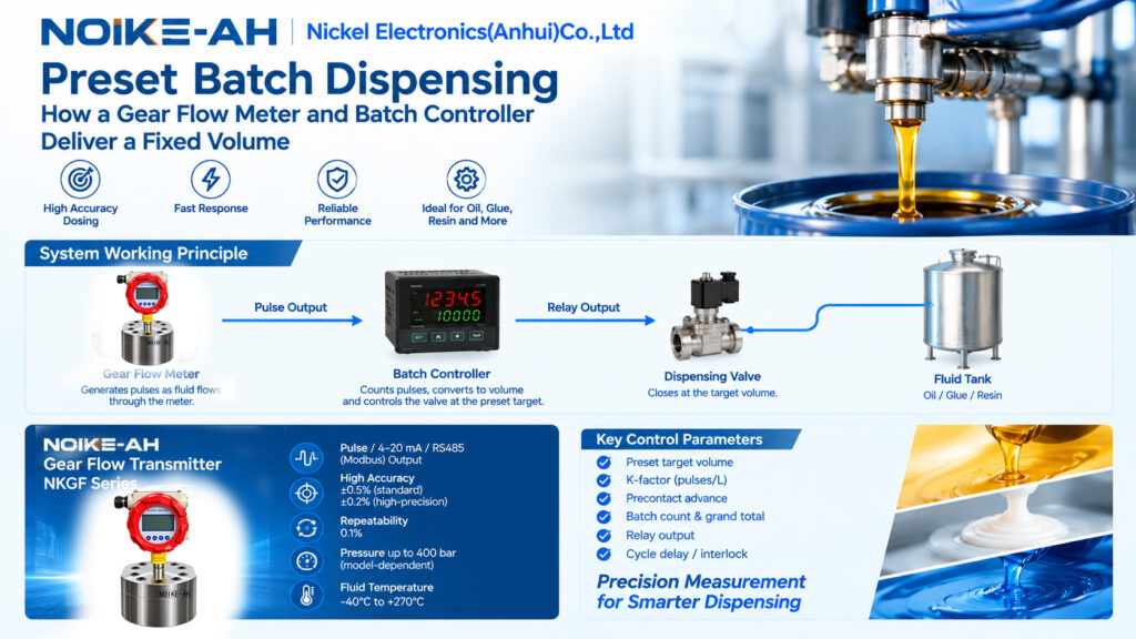
The gear flow meter generates pulses as fluid passes through it. The batch controller counts these pulses, converts them into volume using the configured K-factor, and activates a relay when the accumulated volume reaches the preset target. The relay then triggers the dispensing or inlet valve to close.
Two parameters are particularly important for dispensing accuracy:
- K-factor (pulses/L): Converts the pulse count into a measured fluid volume.
- Precontact advance: Triggers valve closure before the target is reached to compensate for valve response time and fluid continuing to flow during shutoff.
For preset volume dispensing, pulse output is generally the preferred signal because it supports direct pulse counting. A 4–20 mA signal is typically used for continuous flow monitoring, while RS485/Modbus is useful for transmitting flow rates and accumulated totals to a PLC or SCADA system.
Actual dosing accuracy depends on the flow meter, calibration, fluid properties, controller configuration, valve response, and installation conditions.
2. Key Definitions for Gear Flow Meter Batch Dispensing
Understanding the main components and parameters helps ensure that a preset batch dispensing system is configured correctly.
- Batch controller (preset totalizer): A dedicated controller that counts flow meter pulses, compares the accumulated volume with a preset target, and activates an output relay when the target is reached. It is different from a basic flow indicator.
- Preset target (batch quantity): The fixed volume required for one dispensing cycle, entered into the controller in liters or gallons.
- Precontact advance (early shutoff): A volume margin that triggers valve closure before the preset target to compensate for valve-closing delay and residual flow in the line.
- Batch count: The number of completed dispensing cycles.
- Grand total: The cumulative volume dispensed across multiple batches.
- Batch cycle: The operating sequence of starting a cycle, dispensing to the target, closing the valve, confirming batch completion, and resetting the controller for the next dose.
3. How a Preset Batch Dispensing System Works
A typical gear flow meter batch dispensing system operates through the following sequence.
- Set the target volume. The operator enters the required dispensing quantity into the batch controller and initiates the cycle using a button, PLC contact, or automatic start signal.
- Open the dispensing valve. Fluid flows through the gear flow meter, which generates pulses corresponding to the measured volume.
- Count and convert pulses. The batch controller counts the incoming pulses and calculates the accumulated volume using the configured K-factor.Volume (L) = Total Pulses ÷ K-factor (pulses/L)
- Activate the precontact output. As the measured volume approaches the target, the controller triggers an early-shutoff output to compensate for valve response time and residual flow.
- Close the valve at the target. The main relay activates the valve-closing mechanism, and a batch-complete indicator or signal confirms the dispensing cycle.
- Record and reset. The controller updates the batch count and grand total, then resets the batch measurement for the next dispensing cycle.
This arrangement allows the flow meter to measure the delivered volume while the external batch controller manages the preset quantity and valve control.
4. Key Batch Controller Parameters
Correct parameter configuration is essential for repeatable fixed-volume dispensing.
| Parameter | Purpose |
|---|---|
| Preset target volume | Defines the required volume for each dispensing cycle |
| K-factor (pulses/L) | Converts the pulse count into volume based on meter calibration |
| Precontact advance | Triggers early valve closure to compensate for valve and line response |
| Batch count | Records the number of completed dispensing cycles |
| Grand total | Records cumulative dispensed volume |
| Relay output | Activates the valve-closing circuit at the target; the relay rating must match the application requirements |
| Cycle delay / interlock | Controls the pause between cycles and provides a start permissive for safe operation |
The K-factor should be configured using the applicable flow meter calibration data or verified through on-site volume measurement. The precontact advance should be adjusted against actual dispensing results.
5. Which Signal Is Best for Preset Batch Dispensing?
Gear flow transmitters may provide pulse, 4–20 mA, and RS485/Modbus outputs. Each signal serves a different purpose.
| Signal | Role in Batch Dispensing |
|---|---|
| Pulse output | Preferred for preset dispensing because the controller counts pulses to determine the delivered volume and trigger the batch relay |
| 4–20 mA output | Suitable for continuous flow monitoring and low-flow or high-flow alarms; not the preferred method for directly counting an exact dose |
| RS485/Modbus | Transfers flow rate and totalized volume to a PLC or SCADA system for monitoring and data logging; standalone preset shutoff depends on the control system configuration |
For a standalone fixed-volume dispensing application, pulse output connected to a compatible batch controller is generally the most direct configuration. If the application requires centralized automation, Modbus can support integration with a PLC or SCADA system.
The required output type and controller compatibility should be confirmed before installation.

6. Common Batch Dosing Errors and How to Correct Them
Several factors can cause the delivered volume to differ from the preset target.
6.1 Overshooting the Preset Volume
Possible cause: The valve takes time to close, or fluid continues to flow through the line after the closing command.
Recommended correction: Increase the precontact advance so that the controller initiates valve closure earlier. Measure the delivered volume and adjust the setting until the result is satisfactory.
6.2 Under-Dosing
Possible cause: The K-factor is incorrectly configured, or meter slip changes when measuring a thinner or hotter fluid.
Recommended correction: Check the K-factor and verify the delivered volume using a known reference volume under actual operating conditions.
6.3 Inconsistent Batch Volumes
Possible cause: Air entrainment or vortex formation on the suction side can disrupt stable liquid measurement.
Recommended correction: Check the suction conditions, stabilize the fluid supply, and consider appropriate air-release measures where required by the application.
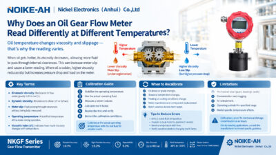
6.4 Changes in Viscosity or Temperature
Possible cause: Changes in fluid viscosity and operating temperature can affect meter slip and the effective volume measurement.
Recommended correction: Verify the K-factor using the actual operating fluid at the working temperature, particularly when process conditions change significantly.
6.5 Valve Fails to Close or Leaks Through the Seat
Possible cause: A worn valve seat, slow actuator, or excessive valve response time can prevent the system from stopping flow as expected.
Recommended correction: Inspect the valve seat, check the valve stroke time, and verify that the valve is suitable for the fluid and operating conditions.

7. Important Limitations of Preset Batch Dispensing
Before designing a fixed-volume dispensing system, consider the following limitations:
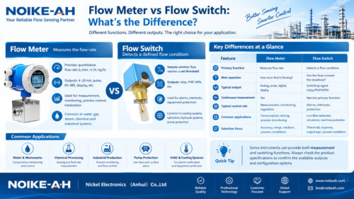
- The gear flow meter does not automatically provide preset shutoff. A meter with pulse output supplies the measurement signal. An external batch controller or suitable control system is responsible for comparing the measured volume with the target and commanding valve closure.
- A 4–20 mA signal is primarily intended for continuous measurement. For direct pulse-count-based preset dispensing, pulse output is generally preferred.
- Controller and valve specifications must be verified separately. Do not assume that a gear flow meter includes a built-in preset function, a specific relay rating, or a particular supply voltage.
- Actual accuracy depends on the complete system. Meter calibration, fluid viscosity, temperature, installation conditions, controller settings, valve response, and residual flow can all affect the delivered volume.
Selecting compatible components and commissioning the system under actual operating conditions are important steps toward repeatable dispensing.
8. Recommended Product: NOIKE-AH NKGF Series Gear Flow Transmitter
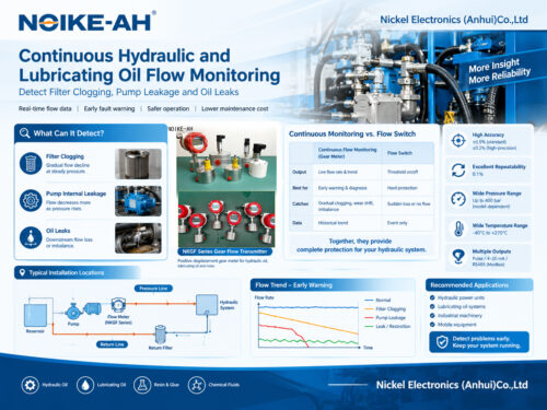
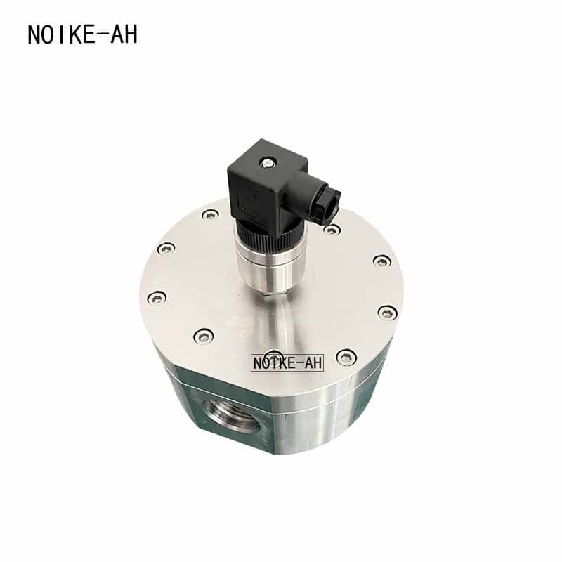
The NOIKE-AH Gear Flow Transmitter NKGF Series provides pulse output, alongside 4–20 mA and RS485/Modbus options, for integration with external batch controllers, totalizers, and compatible monitoring systems.
Published product specifications include:
- Standard accuracy: ±0.5%
- High-precision accuracy: ±0.2%
- Repeatability: 0.1%
- Pressure rating: Up to 400 bar, depending on the model
- Fluid temperature range: -40°C to +270°C
These specifications are model-dependent and should be confirmed for the selected configuration.
For preset batch dispensing applications, confirm the pulse output configuration, K-factor, calibration data, and compatibility with the external batch controller and dispensing valve before wiring and commissioning the system.
Product link: Gear Flow Transmitter NKGF Series
9. Frequently Asked Questions About Gear Flow Meter Batch Dispensing
Q1. Should I use pulse output or 4–20 mA for preset dispensing?
Use pulse output connected to a compatible batch controller for pulse-count-based preset dispensing. A 4–20 mA output is generally used for continuous flow monitoring and alarms rather than direct pulse counting.
Q2. What is precontact advance on a batch controller?
Precontact advance is a setting that triggers valve closure before the preset volume is reached. It compensates for valve-closing delay and residual fluid flow, helping reduce overshoot. The setting should be adjusted based on measured dispensing results.
Q3. How does a batch controller convert pulses into liters?
The controller divides the total number of received pulses by the configured K-factor.
Volume (L) = Total Pulses ÷ K-factor (pulses/L)
The K-factor should be based on the applicable calibration data and verified under actual operating conditions.
Q4. Why does my batch dispensing system exceed the preset target?
Overshoot is commonly associated with valve response delay or fluid continuing to flow after the shutoff command. Increase the precontact advance as appropriate, measure the actual delivered volume, and inspect the valve seat and stroke time.
Q5. Can a gear flow meter close the valve automatically at a preset volume?
Not by itself unless the selected product explicitly includes that function. In the configuration described here, the gear flow meter supplies pulse signals, while an external batch controller counts the pulses and activates the valve relay when the preset target is reached.
10. Related Reading
For more information about gear flow meter selection, high-viscosity fluid measurement, and the NKGF product series, see the following resources:
- How to Choose a Flow Meter for High-Viscosity Liquids
- Measuring High-Viscosity Fluids: Why Gear Flow Meters Are Essential
- Gear Flowmeter Selection Guide
- Gear Flow Transmitter NKGF Series
References
ABB — Flowmeters for Batch Dosing: Preset counters and output contacts.
https://library.e.abb.com/public/634cbfaa510a476a81f464cec9b6d3d1/AG_FB114_EN_A.pdf