Why Does an Oil Gear Flow Meter Read Differently at Different Temperatures? Oil Gear Flow Meter Calibration Guide
Direct Answer: How Does Oil Temperature Affect Gear Flow Meter Readings?
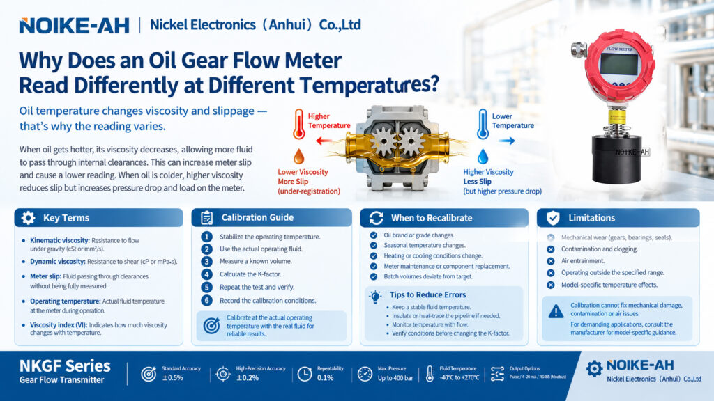
Oil temperature affects gear flow meter accuracy primarily by changing the fluid’s viscosity and the amount of internal slippage. When oil temperature increases, its viscosity generally decreases, allowing more fluid to pass through the clearances between the gears and meter housing without being fully accounted for. This can cause a positive displacement (PD) gear flow meter to under-register the actual flow.
When oil temperature decreases, higher viscosity generally reduces internal slippage but increases pressure drop and the load on the meter. Consequently, a calibration factor established at one temperature may not deliver the same accuracy at another temperature.
For reliable oil flow measurement, calibrate the gear flow meter using the actual operating fluid at its normal working temperature and verify the result with a known volume. Recalibration should also be considered after fluid changes, significant operating-temperature shifts, or maintenance affecting the meter’s internal components.
1. Key Terms in Gear Flow Meter Calibration
Understanding the following terms helps explain why oil temperature can affect flow measurement results.
- Kinematic viscosity (cSt or mm²/s): A measure of a fluid’s resistance to flow under gravity. Oil viscosity generally decreases nonlinearly as temperature increases.
- Dynamic viscosity (cP or mPa·s): A measure of a fluid’s resistance to shear. Dynamic viscosity equals kinematic viscosity multiplied by fluid density when consistent units are used.
- Meter slip: The fluid that passes through internal clearances without being fully accounted for by the meter’s displacement mechanism. Slip generally increases as viscosity decreases and may increase as differential pressure rises.
- Operating temperature: The actual fluid temperature at the flow meter during normal operation, rather than the ambient temperature or a nominal reference temperature.
- Viscosity index (VI): An indicator of how strongly an oil’s viscosity changes with temperature. A higher VI generally indicates a smaller viscosity change over a given temperature interval.
2. Why Oil Temperature Changes Gear Flow Meter Accuracy
2.1 Lower Oil Viscosity Can Increase Internal Slippage
Oil viscosity decreases as temperature rises. The extent of this change depends on the oil formulation and its viscosity-temperature characteristics.
In a positive displacement gear flow meter, rotating gears transport defined volumes of fluid through the measuring chamber. Small clearances between the gears and housing are necessary for operation, but they also allow some fluid to bypass the intended displacement path.
When oil becomes thinner at higher temperatures, it can pass through these clearances more easily. The increase in internal slip may cause the meter to register less volume than actually passes through the system.
This explains why a gear flow meter may produce different readings during cold start-up and after the oil reaches its normal operating temperature.
When oil is cold and highly viscous, internal slip is generally lower. However, the higher viscosity can increase pressure drop, increase mechanical loading, and restrict the usable flow range. Accuracy may also be affected if the meter operates outside its specified flow range.
2.2 Thermal Expansion Can Change Internal Clearances
The gears and housing of a gear flow meter are typically metallic components that expand when heated. Their expansion rates may differ depending on the materials used and the temperature distribution across the meter.
Under certain operating conditions, thermal expansion can alter the clearances between the gears and housing. Excessive temperature may reduce clearances and increase the risk of binding, while different thermal conditions may increase clearances and contribute to greater internal slip.
For most standard installations operating within their specified temperature range, viscosity changes are generally the primary factor to investigate. Thermal expansion becomes more important when the meter operates near or beyond its intended temperature range.
Actual effects depend on the meter’s design, materials, manufacturing tolerances, and operating conditions.
2.3 Why Water Calibration May Not Work for Oil
A gear flow meter calibrated using water may not maintain the same accuracy when installed in an oil system.
Water and oil have different viscosity characteristics. A calibration performed with water establishes a meter factor under the specific conditions of the water test, including its fluid properties, flow rate, and pressure conditions.
When the meter is used with viscous oil, internal slippage can differ significantly. Changes in oil temperature may further alter the amount of slip.
Therefore, a water-based calibration factor should not automatically be assumed valid for oil measurement.
For applications requiring accurate oil dosing or batch control, calibration with the actual operating fluid under representative operating conditions is the preferred approach, provided the meter and calibration equipment are suitable for that fluid.
3. How to Calibrate a Gear Flow Meter at Operating Temperature
Calibrating a positive displacement gear flow meter at its actual operating temperature helps account for the combined effects of fluid viscosity and operating conditions.
Follow these six steps.
Step 1: Stabilize the Operating Temperature
Run the system under normal production conditions until the oil reaches a stable working temperature.
Record the oil temperature at or near the meter. Avoid establishing the final calibration factor while the oil temperature is still changing significantly.
Step 2: Use the Actual Operating Fluid
Use the oil or other fluid that will be measured during normal operation, rather than substituting water or another fluid with different viscosity characteristics.
Ensure that the test fluid, hoses, fittings, and collection equipment are compatible with the application.
Step 3: Measure a Known Volume
Pass a known volume of fluid through the meter and compare the measured volume with the meter’s pulse count or indicated total.
A suitable calibrated volumetric vessel or a gravimetric method may be used. When using a gravimetric method, account for fluid density and the relevant measurement conditions when converting mass to volume.
The reference equipment should have suitable accuracy for the required calibration tolerance.
Step 4: Calculate the Working K-Factor
For a pulse-output meter, calculate the K-factor using the following formula:
K-factor = Number of counted pulses ÷ Reference volume
For example, if the meter generates 10,000 pulses while 100 litres of fluid pass through it:
K = 10,000 ÷ 100 = 100 pulses/L
The resulting K-factor is 100 pulses per litre under the tested conditions.
Enter the appropriate factor into the connected counter, batch controller, or PLC, ensuring that the configured units match the meter and control system.
This example illustrates the calculation method only; it is not a specification for any particular meter model.
Step 5: Repeat the Calibration Test
Repeat the measurement under the same operating conditions and compare the results.
Check whether the measured volume agrees with the reference volume within the application’s required tolerance. If the deviation is outside the acceptable range, investigate the cause before changing the K-factor.
Possible causes include temperature variation, flow-rate differences, air entrainment, contamination, internal wear, and errors in the reference measurement.
Step 6: Record the Calibration Conditions
Document the following information for future verification:
- Fluid type, brand, and grade
- Fluid temperature during calibration
- Test flow rate and pressure conditions
- Reference volume and pulse count
- Calculated K-factor
- Calibration date and verification results
Keeping these records makes it easier to compare measurements over time and distinguish temperature-related changes from mechanical deterioration.
4. When Should an Oil Gear Flow Meter Be Recalibrated?
Recalibration or performance verification should be considered when operating conditions change significantly.
| Operating change | Why verification may be necessary |
|---|---|
| Oil brand or grade changes | Different viscosity characteristics may affect internal slip. |
| Seasonal temperature changes | Changes in the normal working temperature can affect meter performance. |
| Heating or cooling conditions change | The fluid may reach a different viscosity at the meter. |
| Gears, bearings, or seals are serviced or replaced | Maintenance may change the meter’s mechanical condition or clearances. |
| Batch volumes consistently deviate from the target | The cause may be calibration drift, wear, air, or another process issue. |
A fixed recalibration interval should be based on the manufacturer’s recommendations, the application’s accuracy requirements, operating conditions, and historical verification results.
5. Practical Ways to Reduce Temperature-Related Measurement Errors
Maintain a Stable Fluid Temperature
Allow the oil to reach a stable operating temperature before relying on the meter for critical dosing or batch measurements.
Reduce Unnecessary Heat Loss
Where appropriate, use suitable pipe insulation or heat tracing to reduce temperature changes between the heater, pipeline, and meter. Follow the manufacturer’s temperature limits and installation requirements.
Monitor Temperature Alongside Flow
Recording fluid temperature together with flow rate, pulse count, or batch volume helps identify patterns associated with changing viscosity.
A reading that changes with temperature may indicate a fluid-property effect rather than mechanical wear alone.
Verify Before Changing the K-Factor
Do not adjust the K-factor solely because the reading changes. First check whether the fluid temperature, flow rate, pressure, or other operating conditions have changed.
A calibration adjustment may improve results under one set of conditions but introduce errors under another if the underlying cause has not been identified.
6. Limitations: What Calibration Cannot Fix
Temperature is only one factor affecting gear flow meter performance.
- Mechanical wear: Worn gears, bearings, or other internal components can change clearances and measurement performance. Recalibration cannot restore damaged components.
- Contamination and clogging: Particles and deposits can affect gear movement, clearances, and flow passages. The cause must be investigated and corrected.
- Air entrainment: Air bubbles or gas in the fluid can affect the relationship between measured displacement and actual liquid delivery.
- Operating outside the specified range: Excessive temperature, unsuitable pressure, or flow rates outside the permitted range may compromise performance or damage the meter.
- Model-specific temperature effects: A published fluid-temperature rating does not necessarily mean that the meter maintains its nominal accuracy throughout the entire temperature range. Electronic components may also have separate ambient-temperature limits.
There is no universal viscosity threshold or single slip value that applies to every gear flow meter. Performance depends on the meter’s design, clearances, fluid properties, flow rate, differential pressure, and operating conditions.
For demanding applications, consult the manufacturer for model-specific calibration guidance and performance data.

7. NOIKE-AH NKGF Series Gear Flow Transmitter
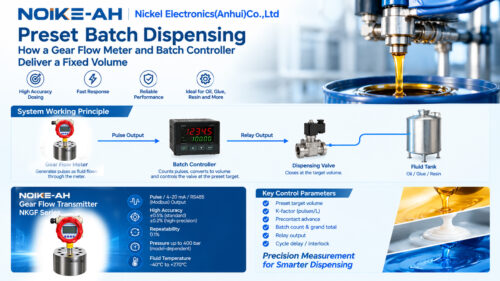
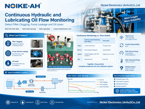
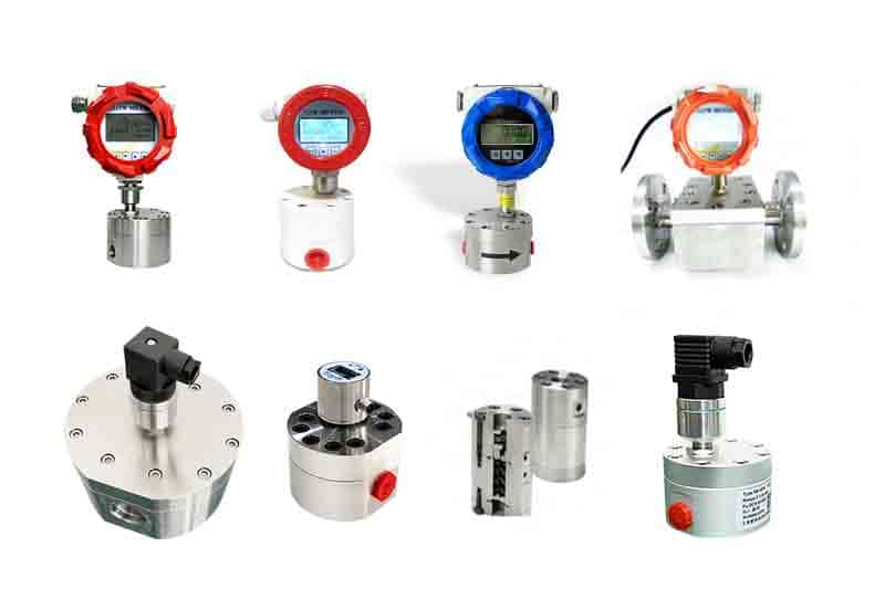
The NOIKE-AH NKGF Series Gear Flow Transmitter is a positive displacement flow measurement product designed for applications involving lubricating oil, hydraulic oil, resin, glue, and other suitable high-viscosity or chemical fluids.
Published product specifications include:
- Standard accuracy: ±0.5%
- High-precision accuracy: ±0.2%
- Repeatability: 0.1%
- Maximum pressure: Up to 400 bar, depending on the model
- Fluid temperature range: -40°C to +270°C
- Output options: Pulse, 4–20 mA, and RS485 (Modbus)
These are published series-level specifications; confirm the exact ratings and configuration of the selected model before application.
For oil flow measurement applications involving significant temperature changes, verify the expected performance under the actual fluid, temperature, pressure, and flow-rate conditions. Do not assume a universal slip value or extrapolate accuracy across the entire temperature range without supporting model-specific data.
Product reference: NOIKE-AH Gear Flow Transmitter NKGF Series
8. Frequently Asked Questions About Gear Flow Meter Temperature Effects
Why does my gear flow meter read low when the oil is hot?
Hot oil generally has lower viscosity, allowing more fluid to pass through internal clearances without being fully accounted for by the meter. This can increase slip and cause under-registration. Verify the meter using the actual operating oil at a stable working temperature.
Can I calibrate a gear flow meter on water and then use it for oil?
A water calibration should not automatically be transferred to oil service. Because water and oil have different viscosity characteristics, the amount of internal slip may change. For accurate oil measurement, calibrate with the actual fluid under representative operating conditions whenever practical.
How often should an oil gear flow meter be recalibrated?
The appropriate interval depends on the application, required accuracy, manufacturer recommendations, and operating history. Verify the meter after fluid changes, significant temperature shifts, relevant maintenance, or repeated deviations in delivered volume.
Does warmer oil always produce a higher flow meter reading?
No. For a positive displacement gear flow meter, warmer oil can increase internal slip and cause the meter to under-register. Colder oil generally reduces slip but increases pressure drop. The actual result also depends on flow rate, differential pressure, meter design, and the control system.
Does thermal expansion significantly affect standard gear flow meters?
Within a meter’s intended operating range, viscosity changes are generally the first factor to investigate. Thermal expansion can become more important at extreme temperatures or where differences in material expansion alter internal clearances. The effect is model-specific.
Can recalibration solve every gear flow meter accuracy problem?
No. Calibration can correct the meter factor under defined operating conditions, but it cannot repair worn gears, damaged bearings, blocked passages, or problems caused by entrained air. Diagnose the underlying issue before adjusting the calibration factor.
9. Related Articles and Product Information
For more information about selecting and applying gear flow meters, explore these related resources:
- How to Choose a Flow Meter for High-Viscosity Liquids
- Measuring High-Viscosity Fluids: Why Gear Flow Meters Are Essential
- Gear Flowmeter Selection Guide
- NOIKE-AH Gear Flow Transmitter NKGF Series
Conclusion
Oil temperature can significantly affect positive displacement gear flow meter readings because it changes viscosity and internal slippage. Higher temperatures generally reduce oil viscosity and may increase under-registration, while lower temperatures increase pressure drop and mechanical loading.
For reliable measurement, stabilize the oil at its normal operating temperature, calibrate with the actual fluid using a known reference volume, verify the K-factor, and maintain records of the calibration conditions.
When accuracy requirements are demanding, confirm the selected meter’s performance with the manufacturer under the intended operating conditions.