How to Choose a Gear Flow Meter for Resin, Glue and Two-Part Coating Dosing: A Selection Guide
1. Direct Answer
For dosing clean, lubricating, high-viscosity resins, glues and two-part coatings, a gear-type positive-displacement (PD) flow meter is usually the right starting point because it counts fixed volumes of fluid directly instead of inferring flow from velocity.
Before choosing a model, confirm five key factors:
- Viscosity range: The minimum, typical and maximum viscosity of each component.
- Dosing flow rate: The minimum, normal and maximum flow rates, together with the required batch volume.
- Operating pressure: Both normal and maximum system pressure.
- Wetted-material compatibility: Compatibility between the fluid, gears, chamber, bearings, seals and cleaning solvents.
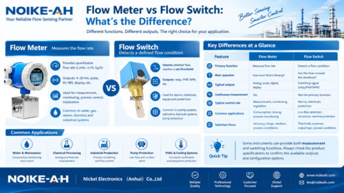
- Output signal: Pulse for batch totals, 4–20 mA for continuous monitoring, or RS485/Modbus for networked control.
Size the meter so that the normal dosing rate sits in the middle of its published flow range rather than selecting it by pipe diameter alone. If the adhesive contains hard fillers or abrasive particles, plan inlet filtration regardless of the technology chosen.
2. Key Takeaways
- Gear positive-displacement flow meters are commonly considered for clean, lubricating, high-viscosity fluids such as resin and glue.
- Viscosity must be evaluated at the actual operating temperature because it changes with temperature and affects meter performance.
- Correct sizing requires the minimum, normal and maximum dosing flow rates, batch volume, system pressure and fluid compatibility.
- Pulse output is suitable for batch counting, while 4–20 mA and RS485/Modbus support continuous monitoring and networked control.
- Hard particles, abrasive fillers and non-lubricating media can accelerate wear and reduce measurement stability.
- The NOIKE-AH NKGF Series is a gear flow transmitter reference for lubricating and high-viscosity fluids. Confirm the specific model’s suitability against the actual operating conditions.
3. What Is a Gear-Type Positive-Displacement Flow Meter?
A gear-type positive-displacement (PD) flow meter is a volumetric instrument in which a pair of precision gears rotates inside a closely matched chamber. Each rotation discharges a fixed, known volume of fluid, and the flow rate is calculated from the rotation count.
Because it measures volume directly, it is largely independent of velocity profile, turbulence and pipe vibration. This is why gear PD meters are commonly considered for viscous liquids where turbine or electromagnetic technologies may be unsuitable.
What Is Resin, Glue and Coating Dosing?
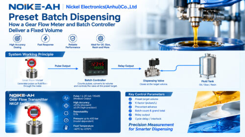
Dosing, also called batching, means delivering a controlled and repeatable volume of a component during each cycle.
A dosing application typically requires a totalizer or batch controller and a pulse signal rather than only a continuous analog reading. The appropriate signal depends on whether the process needs batch-volume control, continuous flow monitoring or integration with a networked control system.

4. How to Choose a Gear Flow Meter: Key Selection Parameters
Before sizing a meter, evaluate every component separately, including resin Part A, hardener or curing agent Part B, solvents and release agents.
| Selection variable | What to confirm | Why it matters |
|---|---|---|
| Medium and lubricating properties | Exact resin or glue grade, solvent-free or solvent-based formulation, lubricating properties, fillers and fibers | Gear PD meters rely on a lubricating film; dry or abrasive media accelerate wear. |
| Viscosity range | Minimum, typical and maximum working viscosity (cP or mPa·s), including temperature-related changes | Each gear model has a usable viscosity window. Outside it, slip or excessive pressure loss may result. |
| Flow rate | Minimum, normal and maximum dosing flow (mL/min or L/min) and batch volume | Sizing around the normal operating point supports accuracy and repeatability. |
| Pressure | Normal operating pressure, maximum system pressure and pump pulsation | Internal bearings and seals have pressure ratings; pulsation can affect signal stability. |
| Temperature | Fluid temperature separately from electronics and ambient temperature; whether the resin is heated | Electronics have their own ambient limits. High fluid temperatures may require a heat sink or remote head. |
| Wetted-material compatibility | Gear, chamber, bushing and seal materials against the specific resin, curing agent and cleaning solvent | Chemical attack can swell seals or corrode gears. Confirm compatibility against the manufacturer’s material list, not just the housing material. |
| Connection and size | Thread or connection standard, port size, isolation and bypass arrangement | Appropriate connections allow servicing without draining the entire line. |
| Output | Pulse for batch totals, 4–20 mA for continuous monitoring, RS485/Modbus for networking | The output must match the dosing controller and automation architecture. |
| Cleanliness | Particle size and required filtration mesh | Hard particles can score the tight clearances between gears. |
| Hazardous area | Zone or classification where solvents or flammable carriers are present | A suitably certified explosion-proof or intrinsically safe model may be required. Certification must be verified rather than assumed. |
How to Select a Flow Meter for Two-Part Coating Dosing
For two-part systems, evaluate Part A and Part B independently. Their viscosities, chemical compositions, flow requirements and material compatibility may differ.
The meter selected for each component must be suitable for that component’s actual operating conditions. Where the process requires a controlled mixing ratio, the flow measurement and batch-control arrangement must support the required dosing strategy.
5. Step-by-Step Selection Procedure
Follow these steps before requesting a quotation or finalizing the meter size.
- Identify every component. Record the fluid grade, minimum, typical and maximum viscosity, and whether the fluid provides adequate lubrication.
- Define the dosing requirement. Record minimum, normal and maximum flow rates, together with the required batch volume.
- Confirm operating conditions. Specify normal and maximum pressure, fluid temperature and ambient temperature separately.
- Verify material compatibility. Check the wetted materials against the actual chemicals and the cleaning solvents.
- Choose the output signal. Select pulse for batch counting, 4–20 mA for continuous monitoring, or RS485/Modbus for networked systems.
- Size the meter correctly. Position the normal operating point within the published flow range and arrange suitable inlet filtration, isolation and bypass where required.
Gear PD vs. Other Flow Meter Technologies for Viscous Dosing
| Technology | Suitability for resin and glue dosing | Main limitation |
|---|---|---|
| Gear PD (micro/circular gear) | Clean, lubricating, viscous fluids at low-to-medium flow; high repeatability for small batches | Requires clean, lubricating media; sensitive to particles; moderate pressure drop |
| Oval gear PD | Larger-volume measurement and transfer of viscous liquids | Larger displacement; particles cause wear; not intended for very low micro-flow applications |
| Screw PD | High-viscosity fluids requiring smooth, low-pulsation delivery | Higher cost; still dependent on wetted-material compatibility and filtration |
| Turbine | Clean, low-viscosity liquids | Higher viscosity increases drag and pressure loss, making it a poor fit for many glue and resin applications |
| Electromagnetic | Conductive liquids | Most resins and glues are non-conductive, so this technology is generally unsuitable |
| Coriolis mass | Direct mass measurement with viscosity-insensitive measurement and density/temperature readout | Higher cost and pressure drop; most appropriate when mass-based or recipe control justifies the investment |
The appropriate technology depends on the fluid properties, dosing rate, accuracy requirements, pressure conditions and process-control objectives.
6. Typical Gear Flow Meter Specifications and Sizing Reference
The following table aggregates publicly published data from comparable gear and positive-displacement meter vendors to provide general sizing expectations. These are industry reference ranges, not the specifications of any particular NOIKE-AH model. Confirm every value against the specific manufacturer’s datasheet before selection.
| Parameter | Typical published range across comparable gear meters |
|---|---|
| Flow range | Micro models from about 0.5 mL/min; common GF-sized models roughly 0.6–20,000 L/h depending on port; larger oval-gear units reach tens of L/min |
| Accuracy | ±0.5% of reading standard; ±0.2% high-precision; repeatability commonly around ±0.1% |
| Viscosity window | Entry micro-gear around 2–200 mPa·s; general gear PD roughly 5–500 cSt; high-viscosity designs extend to about 25,000 mm²/s, with specialty units higher still |
| Pressure | Aluminum body roughly 16–150 bar; stainless steel around 100–400 bar; higher ratings available for custom designs |
| Fluid temperature | Standard roughly -20/-30 to +80°C; high-temperature versions with heat sink or remote head may reach about 150–225°C; verify the separate electronics ambient limit |
| Supply voltage | Most units use 12/24 VDC, often with a 9–26 or 16–30 VDC range; 4–20 mA loop load commonly ≤500 Ω |
| Output | Pulse with K-factor, 4–20 mA, RS485/Modbus; pulse frequency often capped around 5 kHz |
| Wetted materials | Chamber and gears in 304SS/316L or aluminum; seals in FKM/NBR/PTFE; optional PEEK/PP; rolling or sliding bearings; carbide shaft |
| Connection | Threaded G1/8–G2, flange or clamp/tri-clamp, depending on model |
| K-factor | Pulses per liter (P/L), set by factory calibration on the operating fluid; verify on-site with a known volume and track drift to detect wear |
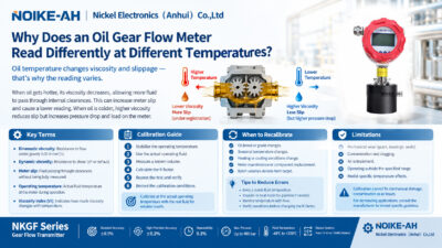
Why Must Viscosity Be Confirmed at Operating Temperature?
Obtain viscosity data at the actual operating temperature rather than relying only on a nominal room-temperature datasheet value.
Viscosity generally decreases as temperature rises. This change can move the fluid outside the meter’s intended operating window and affect measurement performance, pressure loss and repeatability.
7. Gear Flow Meter Limitations and Common Failure Modes
A gear flow meter is not suitable for every fluid or operating condition. The following limitations should be considered during selection and commissioning.
Low-Viscosity Liquids
Water and thin solvents can increase internal slip and reduce measurement accuracy. A gear PD meter is typically a poor match for such applications. The minimum viscosity limit is model-specific, so verify the published operating window rather than relying on a generic threshold.
Abrasive Fillers, Pigments and Hard Particles
Even a low concentration of hard particles can score the close clearances between gears. Install filtration appropriate to the medium and establish an inspection schedule.
Non-Lubricating Media
A lubricating film protects the bearings. Operating a meter with unsuitable non-lubricating media or allowing dry running can shorten its service life.
Excessive Flow or Pressure
Operating beyond the published flow or pressure limits can accelerate bearing wear and affect repeatability. Respect the ratings specified for the selected model.
Confusing Fluid Temperature with Electronics Temperature
A high fluid-temperature rating does not mean the display or electronics can tolerate the same temperature. Verify the electronics’ ambient limit and check whether a heat sink or remote-head arrangement is available.
Pulsating Pump Flow
Pump pulsation may require signal filtering or a pulsation damper. Confirm the appropriate solution with the meter supplier based on the actual system conditions.
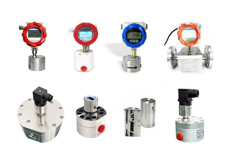
8. Recommended Product: NOIKE-AH Gear Flow Transmitter NKGF Series
The NOIKE-AH Gear Flow Transmitter NKGF Series is a positive-displacement gear meter listed for lubricating and high-viscosity fluids, including lubricating oil, hydraulic oil, resin, glue and chemical fluids.

Published Product Specifications
| Parameter | Published specification |
|---|---|
| Accuracy | ±0.5% standard / ±0.2% high-precision |
| Repeatability | 0.1% |
| Maximum pressure | Up to 400 bar, depending on model |
| Fluid temperature | -40°C to +270°C |
| Output | Pulse / 4–20 mA / RS485 (Modbus) |
The NKGF Series is intended for clean, lubricating, high-viscosity volumetric measurement. Before selecting a specific model for resin, glue or two-part coating dosing, confirm the fluid’s chemical composition, viscosity at operating temperature, flow range, pressure, temperature and wetted-material compatibility through a quotation.
For dosing in classified hazardous areas, select a separately certified intrinsically safe model where required. Do not assume that a standard unit carries hazardous-area certification.
For product details, refer to the NOIKE-AH Gear Flow Transmitter NKGF Series.
9. Frequently Asked Questions (FAQ)
Can a gear PD flow meter measure water or thin solvents?
Usually not well. Thin, low-viscosity liquids increase internal slip and can reduce accuracy. Consider a technology suited to low-viscosity liquids and verify the manufacturer’s published viscosity window.
Does a gear flow meter require a straight pipe run?
Generally, no. The positive-displacement counting principle is insensitive to the flow profile, so straight pipe sections are generally not required.
Why is an inlet filter necessary for resin and glue dosing?
Gear meters have tight internal clearances. Hard particles can cause scoring and measurement drift. A filter selected for the medium helps protect the measuring chamber.
Should I choose pulse or 4–20 mA output for dosing?
Use pulse output when a batch controller counts the total volume delivered. Choose 4–20 mA for continuous flow monitoring, or RS485/Modbus when integrating multiple stations into a networked control system.
Is explosion-proof certification required for glue dosing?
Only when the installation location or carrier solvent falls within a classified hazardous area. Confirm the applicable zone and the certification stated on the selected model’s datasheet. Do not assume that a standard model is certified.
Can one gear flow meter measure both components of a two-part coating?
Each component must be evaluated separately. Confirm the viscosity, flow rate, pressure, chemical compatibility and operating conditions for each fluid, and ensure the selected meter is suitable for its assigned component.
10. Related Reading
- How to Choose a Flow Meter for High-Viscosity Liquids
- Measuring High-Viscosity Fluids: Why Gear Flow Meters Are Essential
- Gear Flowmeter Selection Guide
- Gear Flow Transmitter NKGF Series
Conclusion
Selecting a gear flow meter for resin, glue and two-part coating dosing requires more than matching the pipe size. The key is to verify viscosity at operating temperature, the actual dosing range, pressure, chemical compatibility, cleanliness and output requirements before choosing a model.
For clean, lubricating, high-viscosity fluids, a gear-type positive-displacement meter can be an appropriate solution. The final selection should always be confirmed against the specific model’s published specifications and actual process conditions.
For further details about the appropriate gear flow meter for your application, please contact the NOIKE-AH team for consultation.