Monitoring Cooling Water Flow and Temperature Together: Protecting Heat Exchangers and Pumps from Low Flow and Overheating
1. Why Monitor Cooling Water Flow and Temperature Together?
Monitoring cooling water flow and temperature together provides more comprehensive equipment protection than relying on either signal alone.
A flow switch detects when flow drops below a configured threshold or stops. However, it may not detect gradual fouling or partial restrictions if the flow remains above the switching threshold. A temperature sensor indicates whether cooling performance is deteriorating, but temperature may rise only after heat removal has already become insufficient.
Combining both signals provides earlier warning of cooling-system problems. The flow switch contact triggers an alarm when flow is too low or stops, while the 4–20 mA temperature signal reveals gradual warming caused by fouling, restricted flow, or deteriorating cooling performance.
This combined monitoring approach helps protect heat exchangers, oil coolers, pump cooling jackets, and bearing cooling systems from overheating and gradual performance degradation before a major trip or equipment damage occurs.
2. Key Definitions for Cooling Water Monitoring
2.1 Low-Flow Alarm
A low-flow alarm is triggered when the flow rate falls below a configured threshold or stops, depending on the switching logic. The flow switch contact can be connected to a control system for alarm or equipment protection.
2.2 Overheating
Overheating occurs when process or coolant temperature rises above the acceptable operating range because heat is not being removed sufficiently.
2.3 Fouling Trend
A fouling trend refers to the gradual deterioration of heat-transfer performance as scale, sludge, or biofilm accumulates on heat-transfer surfaces. Flow may remain within the normal range even while temperature gradually increases.
2.4 Supply-Return Temperature Difference (ΔT)
The supply-return temperature difference, or ΔT, is the temperature difference between the coolant supply and return. Changes in ΔT can indicate variations in heat load or cooling performance and may help identify developing fouling when interpreted alongside other operating data.
2.5 Equipment Protection vs. Temperature Indication
A flow switch provides threshold-based protection, while temperature monitoring shows changes and trends over time. Using both signals helps operators identify cooling problems earlier than relying on either signal alone.
3. Why a Flow Switch or Temperature Sensor Alone May Not Be Enough
The following comparison explains the limitations of using only one monitoring signal.
| Monitoring Method | What It Detects | Potential Limitation |
|---|---|---|
| Flow switch only | Complete flow loss or a low-flow condition that crosses the configured threshold | May miss gradual fouling, partial restrictions, or rising temperature while flow remains above the threshold |
| Temperature sensor only | Rising temperature after cooling performance has deteriorated | May react late and cannot independently determine whether the cause is low flow or increased process heat load |
| Flow and temperature monitoring together | Threshold-based low-flow alarms and gradual temperature changes | Provides more comprehensive monitoring, although diagnosis still depends on process conditions and sensor placement |
For example, a flow switch set near the shutoff threshold may remain in its normal state while a heat exchanger gradually accumulates fouling. During this period, temperature may rise even though flow has not fallen below the alarm threshold.
By the time a high-temperature alarm is triggered, the equipment may already have been operating under elevated temperatures.
Conversely, temperature monitoring alone cannot reliably distinguish an increase in process heat load from a cooling-water supply problem.
The key advantage of combined monitoring is that flow status and temperature trends provide complementary information about cooling-system performance.

4. How to Interpret Cooling Water Flow and Temperature Signals Together
Reading flow and temperature signals together helps operators identify potential problems and determine the appropriate inspection or maintenance action.
| Observed Condition | Possible Cause | Recommended Action |
|---|---|---|
| Flow normal, temperature rising | Fouling or scale on heat-transfer surfaces; reduced heat-removal performance | Inspect and clean the heat-transfer surfaces as appropriate; monitor temperature trends |
| Flow decreasing, temperature rising | Partial blockage, clogged strainer, restricted valve, or deteriorating pump performance | Check the strainer, valves, and pump before the condition progresses |
| Flow low or stopped, temperature high | Loss of cooling, or a dry or starved cooling line | Activate the applicable protection logic and restore adequate flow before restarting equipment |
| Flow normal, temperature stable | Cooling conditions appear stable | Continue routine monitoring and maintenance |
These signal combinations provide useful diagnostic guidance, but they do not identify every fault conclusively. Confirm the suspected cause through process inspection and other relevant operating data.
4.1 Flow Normal but Temperature Rising
When flow remains normal while temperature gradually increases, investigate possible fouling, scale accumulation, or declining heat-transfer performance.
Compare the temperature trend with a healthy operating baseline and inspect the heat exchanger or cooler when the deviation warrants action.
4.2 Flow Decreasing and Temperature Rising
A simultaneous reduction in flow and increase in temperature may indicate a clogged strainer, restricted valve, partial blockage, or deteriorating pump performance.
Investigate the cooling-water circuit before the condition develops into a more serious loss of cooling.
4.3 Flow Stopped and Temperature High
Loss of cooling flow combined with high temperature is a potentially serious operating condition.
The flow switch can provide a low-flow or no-flow signal to the control system. Appropriate alarm, interlock, or shutdown logic should be configured according to the equipment manufacturer’s requirements and the application’s risk assessment.
Restore adequate cooling flow and verify safe operating conditions before restarting the equipment.
5. Where Should Flow and Temperature Sensors Be Installed?
Sensor placement should reflect the cooling function being monitored and the specific protection objective.
5.1 Heat Exchanger or Oil Cooler Cooling-Water Inlet
Monitor flow and coolant temperature around the cooling-water inlet to detect inadequate flow and changes in cooling conditions at the point where heat is being removed.
For a more complete assessment of heat-transfer performance, supply and return temperatures may need to be measured separately.
5.2 Pump or Motor Cooling Jacket
A flow switch can provide an alarm when cooling-jacket flow falls below the required threshold. Temperature monitoring adds information about whether the cooling jacket is maintaining acceptable operating conditions.
5.3 Bearing or Spindle Cooling Loop
Combining low-flow protection with temperature trending helps identify cooling interruptions and gradual temperature increases in bearing and spindle cooling systems.
5.4 When Is Additional Measurement Required?
For actual heat-load or thermal energy calculations, a combined alarm-and-indication device is not sufficient by itself.
A suitable measurement arrangement generally requires supply and return temperature measurements, volumetric flow measurement, and the necessary fluid properties and calculation method.
An integrated flow and temperature transmitter supports equipment protection and trend monitoring; it does not replace a dedicated thermal energy measurement system.
6. Important Limitations of Flow and Temperature Monitoring
Before selecting an instrument for cooling-system protection, consider the following limitations.
6.1 Protection and Indication Are Not Thermal Energy Measurement
Flow alarms and temperature indication help identify cooling-system abnormalities. They should not be treated as a calibrated heat or energy meter and should not be used alone for BTU calculations or energy settlement.
6.2 Confirm the Instrument Specifications
Temperature range, measurement accuracy, power supply, and other technical specifications are model-specific. Confirm the requirements of the selected device against the actual operating conditions.
6.3 A Flow Switch Does Not Replace a Volumetric Flow Meter
A flow switch operates at a configured threshold and provides a switching signal. It does not replace a calibrated volumetric flow meter when precise flow measurement or flow totalization is required.
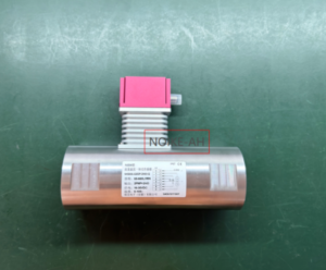
7. NOIKE-AH NK500C Flow and Temperature Integrated Transmitter
The NOIKE-AH Flow & Temperature Integrated Transmitter NK500C monitors flow status and temperature in one device using the thermal dispersion principle.
It is designed to combine flow-related protection and temperature indication in applications where both parameters need to be monitored at the same installation point.
Key features and available configurations include:
- Flow alarm switch output: Provides a switching signal for low-flow or no-flow alarm functions according to the configured threshold and device specifications.
- 4–20 mA temperature output: Transmits temperature data to a compatible PLC, SCADA system, or other control equipment for continuous monitoring and trend analysis.
- Optional temperature switch output: Adds a temperature switching function when specified.
- LED display: Provides local indication of operating information according to the model configuration.
- Adjustable set point: Allows the switching threshold to be adjusted for the application.
- Low pressure loss: Supports applications where minimizing process pressure loss is important.
- Waterproof housing: Provides protection against water ingress according to the specified model rating.
- Optional high-pressure version: Available in a version rated up to 600 bar.
- Optional corrosion-resistant version: Available for applications requiring enhanced resistance to the process medium.
The optional 600 bar high-pressure version and corrosion-resistant configuration should not be assumed to be standard on every unit.
Before ordering, confirm the required temperature range, pressure rating, power supply, probe material, output configuration, and compatibility with the cooling medium through a quotation.
Product Reference: NOIKE-AH Flow & Temperature Integrated Transmitter NK500C
8. Frequently Asked Questions About Cooling Water Flow and Temperature Monitoring
Why should flow and temperature both be monitored in a cooling-water system?
Flow monitoring detects low-flow or no-flow conditions, while temperature monitoring reveals rising temperatures that may indicate fouling or insufficient heat removal. Together, the two signals provide more comprehensive warning than either signal alone.
Can a flow switch alone protect a heat exchanger?
A flow switch can trigger an alarm when flow falls below its configured threshold or stops. However, it may not detect gradual fouling when flow remains above the threshold even as temperature increases and cooling performance deteriorates.
Does the NOIKE-AH NK500C calculate BTU or heat load?
No. The NK500C provides flow alarm functionality and temperature indication. Heat-load or thermal energy calculations require appropriate flow measurement, supply-return temperature difference (ΔT), and the necessary calculation parameters.
How can temperature trends help detect heat exchanger fouling?
Flow may remain within the normal range while temperature gradually rises as heat-transfer performance deteriorates. Tracking temperature against a healthy operating baseline can help identify deviations that warrant inspection and cleaning.
What does the 4–20 mA temperature output do?
The 4–20 mA output sends a continuous temperature signal to a compatible PLC or SCADA system for monitoring, recording, and trend analysis. The flow switch contact can be connected to a digital input for alarm or interlock functions.
The wiring and control logic must be compatible with the selected instrument and the equipment protection requirements.
9. Related Articles and Product Information
Explore the following resources for additional information about flow switches, cooling-system protection, and integrated flow-temperature monitoring.
- CNC Laser Cooling: Flow Switch Protection and Troubleshooting
- Pump Dry-Run Protection: Flow Switch, Level and Current Monitoring
- How Does a Thermal Flow Switch Work?
- NOIKE-AH Flow & Temperature Integrated Transmitter NK500C
10. Technical References
The following references provide additional information about cooling-water flow measurement, heat exchanger performance monitoring, temperature-based condition assessment, and integrated flow-temperature instruments.
Conclusion
Monitoring cooling water flow and temperature together provides a more complete picture of cooling-system performance than relying on a single signal.
A flow switch detects low-flow or no-flow conditions, while temperature trending helps identify gradual warming associated with fouling, restricted cooling, or insufficient heat removal. This combined approach supports earlier intervention and helps protect heat exchangers, oil coolers, pump cooling jackets, and bearing cooling systems.
The NOIKE-AH NK500C Flow & Temperature Integrated Transmitter combines flow alarm functionality and temperature monitoring in one device, providing an integrated option for applications that require both signals at the same location.
Select the appropriate configuration based on the operating temperature, pressure, medium compatibility, installation requirements, and protection strategy.