
CNC Spindle & Laser Tube Cooling Protection: Flow Switch Selection and Troubleshooting
Direct Answer
| Question | Direct Answer |
|---|---|
| Why do CNC spindles and laser tubes need flow switches? | They require continuous liquid cooling to prevent overheating, bearing damage, or tube rupture. A flow switch provides an interlock signal to stop the machine if cooling is lost. |
| What causes cooling flow alarms in small chillers? | Common causes include pump degradation, restricted tubing, air pockets, low coolant level, or a faulty/misadjusted flow switch. |
| Are mechanical flow switches suitable for small cooling loops? | They can be, but in small-diameter tubing with potential debris or vibration, mechanical sensing elements may experience sticking or fluttering. |
| Can a thermal flow switch be used for CNC/Laser cooling? | Yes, provided the pipe size allows proper probe installation, the flow velocity is within the sensor’s detection range, and the medium is compatible. |
| Does a flow switch measure the exact flow rate? | No. It is a threshold device used to confirm whether the flow condition is above or below a safe set point. |
Why CNC Spindles and Laser Tubes Require Flow Interlocks
High-speed CNC spindles and CO2/Fiber laser tubes generate significant heat during operation. If this heat is not continuously removed by a liquid cooling system, the consequences can be severe:
CNC Spindles
Overheating can cause thermal expansion of the shaft, leading to loss of machining precision, bearing failure, and eventual motor burnout.
Laser Tubes
In CO2 lasers, the glass tube relies on water cooling. Loss of flow can cause the tube to crack or shatter due to thermal stress. In solid-state lasers, overheating degrades the laser diodes.
To prevent this, machine manufacturers integrate a Flow Interlock Circuit.
A flow switch is installed in the cooling loop and wired to the machine controller (PLC, VFD, or Laser Power Supply). If the flow drops below the required threshold, the switch opens (or closes) the circuit, triggering an alarm and halting the machine.
Note: It is important to understand that a flow switch is a threshold protection device, not a continuous measurement device.
For a detailed engineering breakdown of these device types, see:
Flow Switch vs. Flow Sensor vs. Flow Meter
Common Causes of Cooling Flow Alarms in Small Cooling Systems
When a CNC machine or laser cutter trips on a “Coolant Flow Low” or “Water Flow Alarm,” the issue is often physical rather than electrical.
The troubleshooting principles here are similar to those used in larger systems, as detailed in:
Chiller Low-Flow Alarm Troubleshooting
| Cause | Possible Symptoms | What to Check | Possible Action |
|---|---|---|---|
| Pump Degradation | Low flow at the outlet; abnormal pump noise. | Pump impeller condition, motor speed, VFD settings. | Replace or repair the pump. (See also: pump dry-run protection methods.) |
| Restricted Tubing / Filters | High pump pressure, low flow downstream. | Inline filters, Y-strainers, kinked or crushed hoses. | Clean filters; replace kinked tubing. |
| Air Pockets / Cavitation | Erratic flow switch behavior, gurgling sounds. | Coolant reservoir level, air bleed valves, hose connections. | Top up coolant; bleed air from the loop. |
| Coolant Degradation | Cloudy fluid, biological growth, sludge. | Coolant condition, concentration of additives. | Flush the system and replace the coolant. |
| Flow Switch Fault | Pump is running and flow is visible, but alarm persists. | Flow switch terminals, sensor indication, wiring. | Test or replace the flow switch. |
Important Engineering Principle:
Do not bypass or short-circuit a flow alarm to keep the machine running. Bypassing the interlock removes the only protection against catastrophic thermal damage to the spindle or laser tube.
Mechanical vs Thermal Flow Switches for Micro-Cooling Loops
Small closed-loop cooling systems, such as industrial chillers used for lasers or spindles, present specific engineering challenges:
- Small pipe diameters
- Low flow rates
- Vibration
- Potential for air entrainment
Mechanical Flow Switches (Paddle / Flapper / Shuttle)
Mechanical switches use a physical element that is pushed by the fluid flow.
Advantages:
- Low cost
- Simple dry-contact output
- No external power required
Challenges in Small Loops:
In small-diameter tubing, mechanical elements can be sensitive to debris, scale, or biological growth.
Vibration from pumps or machine movement can sometimes cause mechanical paddles to flutter, leading to intermittent false alarms.
Additionally, mechanical springs and hinges are subject to wear over time.
Thermal Dispersion Flow Switches
Thermal flow switches detect flow by measuring heat transfer from a heated sensing element to the fluid.
They contain no mechanical moving sensing elements in the flow stream.
Advantages:
- Immune to mechanical sticking from particulates
- Highly resistant to vibration
- Can detect very low flow velocities
Challenges in Small Loops:
- Requires a power supply
- Response time is typically slower than a mechanical snap-action switch (e.g., 1–3 seconds)
- The probe must be properly sized for the pipe diameter to avoid excessive pressure drop
How to Choose a Flow Switch for CNC/Laser Cooling
Follow this sequence to specify the correct flow switch for a cooling loop:
1. Pipe Size and Connection
Small cooling loops often use 8mm, 10mm, or 1/4″ tubing.
Ensure the flow switch connection matches the tubing.
If the pipe is too small for a standard insertion probe, a tee-fitting or manifold installation may be required.
2. Flow Velocity / Rate
Determine the minimum safe flow rate (e.g., L/min) and convert it to flow velocity (cm/s) based on the pipe diameter.
Ensure the switch’s detection range covers this velocity.
3. Medium Compatibility
Cooling loops may use water, deionized water, or water-glycol mixtures.
Verify that the switch’s wetted materials (probe, seals) are compatible with the specific coolant.
4. Electrical Output
Check the machine controller’s input requirements.
Does it need a dry contact (Relay/NO/NC), a PNP/NPN signal, or an analog output?
Verify the voltage supply (e.g., 24V DC).
5. Response Time
Ensure the switch’s response time aligns with the machine controller’s alarm delay.
If the controller expects an instant signal but the switch has a 2-second delay, the machine may still trip erroneously.
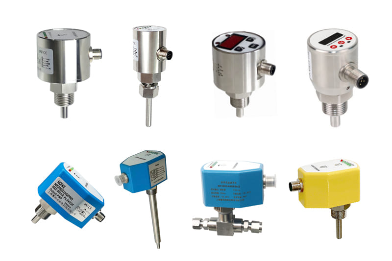
Example: NOIKE-AH NK300 for Cooling System Integration
The NOIKE-AH NK300 can be considered for cooling system flow monitoring when its flow range, medium, pressure, temperature, installation, and output requirements are compatible with the application.
Key Specifications for Evaluation
- Water Flow Setting Range: 1–150 cm/s.
Engineers must calculate if their specific pipe diameter and pump flow rate produce a velocity within this range. - Indication: 6 LEDs provide visual confirmation of flow status, which is useful for troubleshooting machine alarms.
- Output: PNP / NPN / Relay (SPDT NO+NC), allowing flexible integration with various PLCs and machine controllers.
- Construction: Stainless steel probe and IP67 housing, suitable for industrial environments.
Product Reference
NOIKE-AH NK300 Electronic Flow Switch
Installation Consideration for Small Pipes
Because the NK300 is an insertion-style thermal flow switch, the probe must be fully inserted into the pipeline to ensure accurate measurement.
For very small diameter tubing (e.g., < 10mm), direct insertion may not be feasible without blocking the flow.
In such cases, engineers should consider installing the switch in a larger bypass line, a manifold, or using appropriate tee-fittings to accommodate the probe size.
When Is a Thermal Flow Switch NOT the Right Choice?
Extremely Small Tubing
If the pipe diameter is too small to accommodate the sensor probe without creating a severe restriction, a mechanical shuttle switch or a dedicated inline micro-flow sensor may be more appropriate.
Highly Aerated Coolant
If the cooling loop contains a high volume of entrained air bubbles, the thermal transfer properties will become erratic, potentially causing false readings.
Instantaneous Shutdown Requirements
If the control system requires a sub-millisecond response time to prevent immediate damage, the thermal response time (typically 1–3 seconds) may be too slow.
Unverified Media
For specialized laser coolants or aggressive chemical additives, medium compatibility must be verified directly with the manufacturer.
Frequently Asked Questions (FAQ)
Why does my CNC machine show a “Spindle Coolant Flow Alarm” even though the pump is running?
This indicates that while the pump is running, the flow velocity at the switch location is below the required threshold.
Common causes include a clogged filter, a worn pump impeller, air trapped in the line, or a faulty flow switch.
Can I replace a mechanical flow switch with a thermal flow switch?
Yes, provided the thread connection, pipe diameter, electrical output (e.g., Relay vs PNP), and power supply requirements are compatible.
Thermal switches are often used to replace mechanical switches in environments where vibration or debris causes mechanical sticking.
How do I test a flow switch on a laser chiller?
With the pump running, check if the flow switch indicators (LEDs) show flow.
Use a multimeter to verify if the output signal changes state when the flow is adequate.
If the switch has an adjustable potentiometer, consult the manual for calibration steps.
Does a thermal flow switch work with water-glycol mixtures?
Thermal flow switches measure heat transfer, which is affected by the fluid’s thermal properties.
For water-glycol mixtures, medium compatibility and calibration accuracy must be verified directly with the manufacturer before specifying the device.
What is the difference between a flow switch and a flow meter in a CNC cooling system?
A flow switch only confirms if the flow is above or below a safe threshold (used for machine interlock).
A flow meter measures and displays the exact flow rate (e.g., L/min) for monitoring or balancing purposes.
Where should the flow switch be installed in a cooling loop?
It should be installed in a section of pipe that is completely full of liquid, typically on the discharge side of the pump or downstream of the heat exchanger, avoiding areas with severe turbulence or air pockets.
Internal References & Resources
Core Concepts
Flow Switch vs. Flow Sensor vs. Flow Meter: Key Differences and Selection Guide
Chiller Protection Application
Chiller Low-Flow Alarm Troubleshooting: Causes, Flow Switch Testing, and Solutions
Pump Protection Application
Pump Dry-Run Protection: Flow Switch vs. Level Switch vs. Current Monitoring
Technology Comparison
Thermal Flow Switch vs Mechanical Flow Switch
Product Specifications
NOIKE-AH NK300 Electronic Flow Switch
RFQ / Product Inquiry
For CNC spindle and laser tube cooling applications, provide the pipe size, minimum flow requirement, cooling medium, electrical output, power supply, operating conditions, and installation requirements when selecting a flow switch.
NOIKE-AH — Professional Flow Instrument Manufacturer



