
Pump Dry-Run Protection: Flow Switch vs. Level Switch vs. Current Monitoring
Direct Answer
| Question | Direct Answer |
|---|---|
| What is pump dry running? | Operating a pump without sufficient liquid inside the casing, which can lead to rapid seal failure, bearing damage, and motor burnout. |
| What is the best protection method? | There is no single universal method. Flow switches prove actual discharge flow conditions, level switches prevent starting on empty tanks, and current monitors detect electrical load changes. |
| Does current drop when a pump runs dry? | For many centrifugal pumps, yes (current drops). For positive displacement (PD) pumps, no (current may spike or the motor may stall). |
| Where should a flow switch be installed for pump protection? | On the discharge line, downstream of the pump, to confirm the flow condition at that specific point. |
| Can a thermal flow switch protect a pump? | Yes, thermal dispersion flow switches can be used on discharge lines to detect low-flow or no-flow conditions, particularly where mechanical sticking of the sensing element is a concern. |
Key Takeaways
- Pump dry running occurs when a pump operates without sufficient liquid inside the casing.
- There is no single universal dry-run protection method for every pump and failure condition.
- Flow switches detect low or no flow at the sensing location.
- Level switches monitor the liquid level in the supply tank or sump.
- Current or power monitoring detects changes in the motor’s electrical load.
- Pressure switches detect pressure conditions at the suction or discharge point.
- Centrifugal and positive displacement pumps can have different electrical responses during dry running.
- A comprehensive pump protection strategy may combine a level switch with a flow switch.
What Is Pump Dry Running and Why Is It Dangerous?
Pump dry running occurs when a pump operates with insufficient liquid in its casing. Pumps are designed to move and be cooled/lubricated by the process fluid. When that fluid is absent, the internal components experience extreme friction and heat.
The consequences of dry running include:
Mechanical Seal Failure
Mechanical seals can be damaged rapidly when a pump operates without adequate liquid lubrication. The actual time to damage depends on the pump, seal design, operating speed, and fluid conditions.
Bearing and Shaft Damage
Excessive heat and vibration degrade bearings and can cause shaft deflection.
Motor Burnout
The motor may overheat due to the loss of the cooling effect provided by the pumped fluid or due to abnormal electrical loads.
Cavitation and Vibration
Severe vibration can damage piping supports and connected equipment.
Because damage can occur quickly, automated dry-run protection is an engineering requirement for most critical and unattended pumping systems.
The Physics of Pump Protection: Centrifugal vs. Positive Displacement
Before selecting a protection method, engineers must understand how different pump types behave when they lose prime. This physical distinction dictates which protection methods are viable.
Centrifugal Pumps
Centrifugal pumps rely on the kinetic energy imparted to the fluid by an impeller.
Dry Run Behavior
Air is significantly less dense than water. When a centrifugal pump loses prime and pumps air, the mechanical load on the impeller generally drops.
Electrical Signature
For many centrifugal pumping systems, loss of liquid load can reduce hydraulic load and therefore reduce motor current. The actual electrical response depends on the pump, motor, speed control, and system operating point.
Positive Displacement (PD) Pumps
PD pumps, such as gear, lobe, progressive cavity, and diaphragm pumps, trap a fixed volume of fluid and force it into the discharge pipe.
Dry Run Behavior
These pumps will continue to attempt to move fluid. If the discharge line is pressurized or if internal friction increases due to lack of lubrication, the mechanical load increases.
Electrical Signature
The motor may draw higher current, or the drive may stall/trip on overload.
Comparing the 4 Main Dry-Run Protection Methods
Engineers typically use one or a combination of the following methods to protect pumps.
Before selecting a device, it is important to understand the difference between a flow switch and a flow meter to ensure the correct signal type is specified for the control system.
Internal Reference:
Flow Switch vs. Flow Sensor vs. Flow Meter
Method 1: Flow Switches — Direct Flow Detection
A flow switch installed on the discharge line can confirm whether the flow condition at that point has reached the configured threshold.
Primary Detection
Low / no flow at the sensing location.
Best For
Confirming actual liquid movement; systems where downstream blockages or closed valves might cause dead-heading.
Limitation
Must be installed on a fully flooded pipe section; cannot detect an empty supply tank before the pump starts.
Method 2: Level Switches — Supply-Side Protection
A level switch, such as float, ultrasonic, or capacitive type, is installed in the supply tank or sump.
Primary Detection
Low liquid level in the tank.
Best For
Batch processes, sump pumping, and preventing the pump from ever losing prime.
Limitation
Does not protect against downstream blockages, suction line leaks, or internal pump failures, such as a sheared impeller.
Method 3: Current / Power Monitoring — Motor-Side Protection
A current relay or VFD (Variable Frequency Drive) monitors the electrical load of the motor.
Primary Detection
Change in motor electrical load.
Best For
Submersible pumps, deep well pumps, and applications where installing inline sensors is difficult.
Limitation
Current-underload protection based on the assumption that dry-running causes a reduction in motor current is generally not suitable as a standalone dry-run detection method for Positive Displacement pumps.
Method 4: Pressure Switches — Suction / Discharge
Primary Detection
Pressure condition at the sensing point.
Suction Pressure Switch
Detects loss of supply pressure, useful for booster pumps.
Discharge Pressure Switch
Detects dead-heading, pressure too high, or loss of prime, pressure too low.
Limitation
Pressure does not always equal flow. A system can have static pressure but zero flow, such as a dead-head condition.
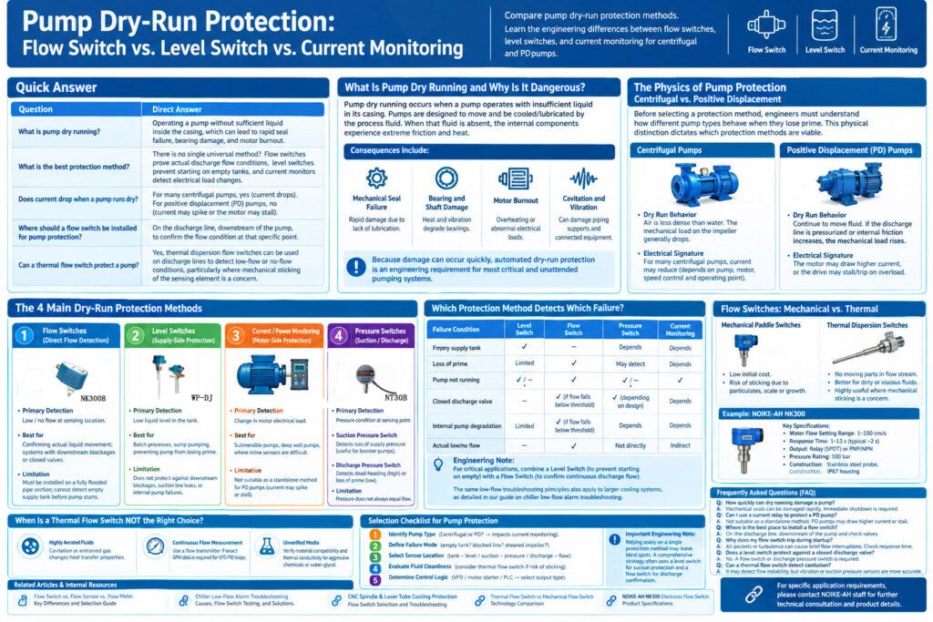
Which Pump Protection Method Detects Which Failure?
To design a robust protection scheme, engineers must map the sensor type to the specific failure mode it can reliably detect.
| Failure Condition | Level Switch | Discharge Flow Switch | Pressure Switch | Current Monitoring |
|---|---|---|---|---|
| Empty supply tank | ✓ | — | Depends | Depends |
| Loss of prime | Limited | ✓ | May detect | Depends |
| Pump not running | ✓ / — | ✓ | ✓ / — | ✓ |
| Closed discharge valve | — | ✓ (if flow falls below threshold) | ✓ (depending on design) | Depends |
| Internal pump degradation | Limited | ✓ (if flow falls below threshold) | Depends | Depends |
| Actual low/no flow | — | ✓ | Not directly | Indirect |
Note: For critical applications, engineers often combine a Level Switch (to prevent starting on empty) with a Flow Switch (to confirm continuous discharge flow).
The same low-flow troubleshooting principles used here also apply to larger cooling systems, as detailed in our guide on Chiller Low-Flow Alarm Troubleshooting.
Deep Dive: Flow Switches for Pump Protection
When direct flow confirmation is required, engineers must choose between mechanical and thermal dispersion flow switches.
Mechanical Paddle Switches
Mechanical switches are widely used due to their low initial cost.
However, in pump protection applications, fluids may contain particulates, scale, or biological growth. These contaminants can cause the mechanical paddle to stick in the “flow proven” position, rendering the protection useless when the pump actually loses prime.
Thermal Dispersion Flow Switches
Thermal dispersion flow switches utilize a heated sensing element.
Because the sensing mechanism contains no mechanical moving sensing elements in the flow stream, they are highly useful in applications where mechanical sticking of the sensing element is a concern.
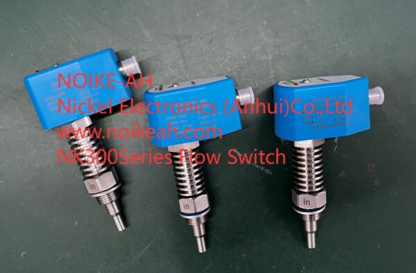
Recommended Instrument: NOIKE-AH NK300 for Pump Protection
Example: NOIKE-AH NK300 for Pump Protection
The NOIKE-AH NK300 can be considered for pump discharge flow monitoring when its flow range, medium, pressure, temperature, installation, and output requirements are compatible with the application.
Key Specifications for Evaluation
| Parameter | NK300 Specification |
|---|---|
| Water Flow Setting Range | 1–150 cm/s |
| Response Time | 1–13 seconds, typical approximately 2 seconds |
| Output | Relay (SPDT) or PNP/NPN |
| Pressure Rating | 100 bar |
| Construction | Stainless steel probe and IP67 housing |
Water Flow Setting Range
1–150 cm/s
Allows precise setting of the minimum safe flow threshold.
Response Time
The NK300 has a specified response time of 1–13 seconds, with a typical response time of approximately 2 seconds.
The appropriate response behavior should be evaluated against the pump startup sequence and the manufacturer’s application requirements.
Output
Relay (SPDT) or PNP/NPN for direct integration into motor contactor circuits or PLCs.
Pressure Rating
100 bar
Accommodates high-pressure discharge lines.
Construction
Stainless steel probe and IP67 housing suitable for harsh pump rooms and washdown environments.
Product Reference:
NOIKE-AH NK300 Electronic Flow Switch
When Is a Thermal Flow Switch NOT the Right Choice for Pump Protection?
Highly Aerated Fluids
If the pump is cavitating heavily or the fluid contains a high volume of entrained gas, the thermal transfer properties change erratically.
Continuous Flow Measurement
If the control system requires exact GPM data for VFD PID loops, a flow transmitter is required.
Unverified Media
For aggressive chemicals or specific water-glycol concentrations, wetted material compatibility and thermal conductivity must be verified with the manufacturer prior to specification.
Selection Checklist for Pump Protection
Follow this sequence when selecting a pump dry-run protection method.
1. Identify Pump Type
Is it Centrifugal or Positive Displacement?
This impacts the viability of current underload monitoring.
2. Define the Failure Mode
Are you protecting against:
- An empty tank?
- A blocked discharge line?
- A sheared impeller?
3. Select the Sensor Location
Will the sensor be:
- In the tank — Level
- On the suction line — Pressure
- On the discharge line — Flow
4. Evaluate Fluid Cleanliness
If the application presents a risk of mechanical sticking, specify a thermal dispersion flow switch over a mechanical paddle switch.
5. Determine Control Logic
Does the sensor need to interface with:
- A VFD
- A hard-wired motor starter
- A PLC
Select the appropriate output:
- Relay
- PNP
- NPN
- 4–20 mA
Important Engineering Note:
Relying solely on a single protection method may leave blind spots in the system design. A comprehensive pump protection strategy often utilizes a level switch for suction protection and a flow switch for discharge confirmation.
Frequently Asked Questions (FAQ)
How quickly can dry running damage a pump?
Mechanical seals can be damaged rapidly when a pump operates without adequate liquid lubrication. The actual time to damage depends on the pump, seal design, operating speed, and fluid conditions. Immediate, automated shutdown is required.
Can I use a current relay to protect a positive displacement pump?
Current-underload protection based on the assumption that dry-running causes a reduction in motor current is generally not suitable as a standalone dry-run detection method for Positive Displacement pumps.
PD pumps may draw higher current or stall when running dry.
Where is the best place to install a flow switch for pump protection?
The flow switch should be installed on the discharge line, downstream of the pump and any check valves, in a section of pipe that remains completely full of liquid during normal operation.
Why does my flow switch trip during pump startup?
During startup, air pockets or transient turbulence can cause brief flow interruptions.
The response time of the flow switch must be evaluated against the pump startup sequence to ensure it aligns with the system’s transient behavior.
Does a level switch protect against a closed discharge valve?
No.
A level switch only monitors the supply tank. If the discharge valve is closed, the pump will dead-head, building maximum pressure with zero flow.
A flow switch or discharge pressure switch is required to detect this condition.
Can a thermal flow switch detect if a pump is cavitating?
Severe cavitation introduces vapor bubbles into the fluid stream, which alters the heat transfer rate at the thermal sensor.
While it may detect the resulting flow instability, dedicated vibration sensors or suction pressure monitors are generally more accurate for early cavitation detection.
Internal References & Resources
Core Concepts
Flow Switch vs. Flow Sensor vs. Flow Meter: Key Differences and Selection Guide
Chiller Protection Application
Chiller Low-Flow Alarm Troubleshooting: Causes, Flow Switch Testing, and Solutions
CNC/Laser Cooling Application
CNC Spindle & Laser Tube Cooling Protection: Flow Switch Selection and Troubleshooting
Technology Comparison
Thermal Flow Switch vs Mechanical Flow Switch
Product Specifications
NOIKE-AH NK300 Electronic Flow Switch
Conclusion
A comprehensive pump protection strategy often utilizes a level switch for suction protection and a flow switch for discharge confirmation.
The appropriate protection method depends on the pump type, failure mode, sensor location, fluid conditions, and control logic.
For direct discharge-flow confirmation, a thermal dispersion flow switch such as the NOIKE-AH NK300 can be considered when its flow range, medium, pressure, temperature, installation, and output requirements are compatible with the application.
RFQ / Product Inquiry
For pump dry-run protection applications, evaluate the following parameters before selecting a device:
- Pump type
- Failure mode
- Sensor location
- Fluid conditions
- Flow condition
- Pressure
- Temperature
- Control system
- Required output
For applications where direct discharge flow confirmation is required, the NOIKE-AH NK300 Electronic Flow Switch can be evaluated based on the actual application requirements.
NOIKE-AH
Professional Flow Instrument Manufacturer



