
Chiller Low-Flow Alarm Troubleshooting: Causes, Flow Switch Testing, and Solutions
Direct Answer
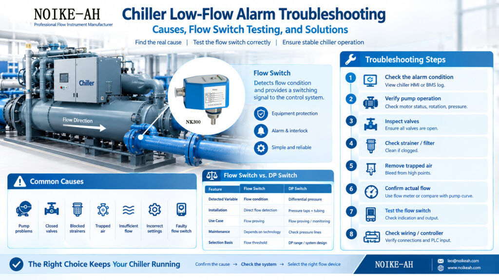
A chiller may show a low-flow alarm because of pump problems, closed valves, blocked strainers, trapped air, insufficient flow, incorrect switch settings, or a faulty flow switch.
A flow switch detects whether the flow condition crosses a defined threshold and provides a switching signal to the control system. It does not measure or display the exact volumetric flow rate.
The recommended troubleshooting sequence is to check the pump, valves, strainer/filter, trapped air, and actual flow condition before testing the flow switch and wiring.
A thermal flow switch can be an alternative to a mechanical flow switch when the medium, flow range, pressure, temperature, connection, and output requirements are compatible.
Key Takeaways
- Common causes of chiller low-flow alarms include pump problems, closed valves, blocked strainers, trapped air, insufficient flow, incorrect switch settings, and faulty flow switches.
- A flow switch is primarily a threshold/proving device rather than a continuous flow meter.
- Actual flow should be confirmed before replacing or testing the flow switch.
- Mechanical and thermal/electronic flow switches use different sensing principles and require different testing procedures.
- Flow-switch selection should be checked against the chiller manufacturer’s minimum flow requirement, actual piping design, and equipment control logic.
What Does a Flow Switch Do in a Chiller?
A flow switch is a threshold-based switching device commonly used for flow proving, alarms, and equipment protection. Its primary function is to detect whether the flow condition crosses a defined threshold.
When flow is adequate, the switch changes its electrical contact state, providing a “flow-proven” signal to the chiller’s microprocessor or the building management system (BMS). If flow drops below the set threshold, the signal changes, which may trigger an alarm or inhibit compressor operation. The exact control action depends on the chiller manufacturer’s control logic.
This interlock is critical to prevent refrigerant from freezing the stagnant water inside the heat exchanger tubes, which can cause catastrophic tube ruptures.
Note: A flow switch is not a flow meter. It does not measure or display the exact volumetric flow rate (e.g., GPM or L/min); it only confirms if the flow condition is above or below a safe limit.
For a detailed engineering breakdown of these devices, see our guide on Flow Switch vs. Flow Sensor vs. Flow Meter:
https://www.noikeah.com/blog/flow-switch-vs-flow-sensor-vs-flow-meter/
What Causes a Chiller Low-Flow Alarm?
When a chiller trips on a low-flow fault, the root cause is frequently a physical restriction in the water loop or a failure in the pumping system, rather than a failure of the sensor itself.
| Cause | Possible Symptoms | What to Check | Possible Action |
|---|---|---|---|
| Clogged Strainer / Filter | High pump discharge pressure; low pressure after the strainer. | Pressure differential across the Y-strainer. | Isolate, open, and clean the strainer basket. |
| Air Trapped in Piping | Erratic flow switch behavior; gurgling noises in the evaporator. | Automatic air vents on system high points. | Manually bleed air from the heat exchanger and high-point vents. |
| Pump Degradation | Lower than normal pump discharge pressure; abnormal motor amps. | Pump rotation, impeller condition, VFD frequency. | Repair pump; verify VFD settings and motor coupling. (See also: pump dry-run protection — [INSERT URL: Article 2]) |
| Closed / Failed Valve | Zero or severely restricted flow downstream. | Position indicators on isolation and butterfly valves. | Manually open valves; repair failed actuator. |
| Mechanical Switch Jamming | Pump is running and pipe is full, but switch remains open. | Paddle movement; physical scale buildup on the hinge. | Clean the paddle; replace the switch if the hinge is seized. |
| Incorrect Switching Point | Alarm triggers during normal system startup or minor flow fluctuations. | Potentiometer setting or DIP switch configuration. | Recalibrate the switching threshold to match OEM requirements. |
| Faulty Wiring / PLC Input | Switch physically actuates, but chiller panel shows no flow. | Voltage and continuity at the controller input terminals. | Repair broken wires; verify PLC input card status. |
Important Engineering Principle:
Do not replace the flow switch before confirming that actual flow is adequate. A low-flow alarm does not automatically mean the flow switch is faulty. It often means the switch is doing exactly what it was designed to do: detecting a genuine lack of water flow.
How to Troubleshoot a Chiller Low-Flow Alarm
Troubleshooting Flowchart
Low-Flow Alarm

      ↓

Is the pump running?

 ├─ No → Check pump/control

 └─ Yes

      ↓

Are valves open?

 ├─ No → Open / inspect valves

 └─ Yes

      ↓

Is the strainer blocked?

 ├─ Yes → Clean / inspect

 └─ No

      ↓

Is there trapped air?

 ├─ Yes → Vent system

 └─ No

      ↓

Is actual flow adequate?

 ├─ No → Resolve hydraulic problem

 └─ Yes

      ↓

Check flow switch

      ↓

Check output / wiring / controller
Follow this systematic sequence to isolate the fault safely and efficiently.
Step 1: Confirm the Alarm Condition
What to check:
The chiller HMI or BMS alarm log.
Why it matters:
Determines if the fault is an active hard-wired trip or a historical communication glitch.
What the result means:
If the alarm resets immediately and does not return, it may have been a transient pressure spike or air pocket. If it persists, proceed to physical checks.
Step 2: Check Pump Operation
What to check:
Pump motor status, rotation direction, and discharge pressure gauge.
Why it matters:
The pump is the prime mover. If the pump is off, running backward, or cavitating, no flow switch will close.
What the result means:
Normal pressure but no flow alarm indicates a sensor/wiring issue. Low pressure indicates a system or pump fault.
Step 3: Check Valves
What to check:
All manual isolation valves, check valves, and balancing valves in the active loop.
Why it matters:
A single closed valve during maintenance will halt the entire circuit.
What the result means:
Ensure all valves are locked in the fully open position.
Step 4: Inspect Strainer / Filter
What to check:
The Y-strainer or inline filter upstream of the chiller.
Why it matters:
Strainers capture debris but create a severe pressure drop when loaded, reducing velocity below the switch threshold.
What the result means:
A high differential pressure across the strainer confirms a blockage requiring cleaning.
Step 5: Check Trapped Air
What to check:
Air vents on the chiller barrel and the highest points of the piping network.
Why it matters:
Air pockets act as physical barriers to water flow and cause mechanical paddle switches to flutter and drop out.
What the result means:
Bleeding the system restores continuous liquid contact with the sensor.
Step 6: Verify Actual Flow
What to check:
Use an ultrasonic clamp-on flow meter on the exterior of the pipe, or compare pump curve data with current pressure readings.
Why it matters:
Confirms whether water is actually moving at the required velocity.
What the result means:
If actual flow is adequate but the alarm persists, the fault is isolated to the flow switch or its electrical circuit.
Step 7: Test the Flow Switch
What to check:
Sensor indication (LEDs), physical movement (if mechanical), and electrical output.
Why it matters:
Isolates the sensor from the piping system.
What the result means:
Proceed to the detailed testing procedures below.
Step 8: Check Wiring / Controller Input
What to check:
Terminal block connections, cable continuity, and PLC input LEDs.
Why it matters:
Vibration and moisture can cause wire fatigue or short circuits.
What the result means:
Repairing the circuit restores the signal path to the chiller controller.
How Do You Test a Chiller Flow Switch?
Safety Notice: Before removing or electrically testing a flow switch, follow the equipment manufacturer’s safety procedure and applicable lockout/tagout (LOTO), isolation, depressurization, and electrical safety requirements.
Exact test procedures depend on the installed model and manufacturer documentation. However, general principles apply to the two main categories.
Mechanical Paddle Switch
- Visual/Physical Inspection: With the system isolated and drained, remove the switch from the pipe fitting. Inspect the paddle for heavy scale, biofilm, or physical deformation.
- Movement Test: Manually push the paddle to simulate water flow. It should move smoothly and return via the internal spring.
- Continuity Test: Use a digital multimeter set to continuity (Ohms) on the switch terminals. The circuit should change state (NO to NC, or vice versa) when the paddle is deflected.

Thermal / Electronic Flow Switch
- Initialization: Ensure the device has been powered on for the required initialization time (e.g., 8 seconds) before expecting a stable output.
- LED Indication: With the pump running, observe the sensor indicators. Some thermal flow switches provide LED indicators for flow status or sensor condition. The meaning of each LED depends on the specific model. (Note: The NK300 uses six LEDs for flow indication).
- Output Verification: Use a multimeter to check the voltage at the output wires. For a PNP output, the output should switch toward the positive supply voltage when the configured switching condition is met. The exact voltage depends on the device’s supply voltage and output design. For a Relay output, check for contact continuity.
- Threshold Adjustment: If the switch features a potentiometer, refer to the OEM manual for the specific calibration sequence to adjust the switching point.
Why Do Mechanical Flow Switches Sometimes Fail?
Mechanical flow switches (paddle or vane types) rely on the physical force of moving water to push a hinged element, which actuates a microswitch. While they remain appropriate for many clean, simple applications, they are subject to specific physical limitations:
- Contamination and Scale: In open condenser water loops, calcium scale or suspended solids can build up on the paddle or the hinge pin, increasing friction until the switch can no longer move.
- Mechanical Fatigue: Repeated cycling and water hammer can weaken the return spring over time.
- Installation Sensitivity: If a paddle is trimmed incorrectly for the specific pipe diameter, it may not extend far enough into the flow stream to detect low-flow conditions accurately.
These failure modes do not mean mechanical switches are inherently flawed; rather, their suitability depends heavily on water quality and maintenance schedules.
Flow Switch vs Differential Pressure Switch for Chillers
In large commercial HVAC systems, engineers must choose between direct flow switches and differential pressure (DP) switches to prove flow across the chiller barrel. Neither technology is universally better. Selection depends on chiller design, manufacturer requirements, piping configuration, and control philosophy.
| Factor | Flow Switch | Differential Pressure (DP) Switch |
|---|---|---|
| Physical Variable Detected | Threshold-based flow detection | Differential pressure |
| Installation Concept | Direct flow detection via process connection | Pressure difference across defined sensing points |
| Typical Use | Direct flow proving | Differential-pressure based monitoring/proving |
| Maintenance Considerations | Depends on technology (e.g., cleaning mechanical paddles) | Pressure sensing connections and impulse tubing require maintenance |
| Selection Basis | Flow threshold requirements | Differential pressure range / system design |
A DP switch detects differential pressure rather than directly detecting the flow condition. Its suitability therefore depends on the relationship between pressure differential and the required flow condition in the specific chiller system.
When Is a Thermal Dispersion Flow Switch a Practical Alternative?
Thermal dispersion technology eliminates mechanical sensing movement, which can be useful where mechanical sticking or wear is a concern.
Working Principle
- The sensor probe contains a heated sensing element and a reference temperature element.
- As fluid flows past the probe, it carries heat away from the heated element.
- The rate of heat transfer changes based on the fluid movement.
- The internal electronics calculate this thermal difference and change the output state when the flow crosses the predefined switching threshold.
Because the sensing process relies on heat transfer rather than physical displacement, the sensing mechanism contains no mechanical moving sensing elements in the flow stream.
Example: NOIKE-AH NK300 Electronic Flow Switch
The NOIKE-AH NK300 (https://www.noikeah.com/product/electronic-flow-switch-nk300/ is an electronic flow switch using thermal dispersion technology for threshold-based flow detection.
| Parameter | NK300 Specification |
|---|---|
| Principle | Thermal Dispersion |
| Medium | Water, Oil, Air |
| Water Flow Setting Range | 1–150 cm/s |
| Oil Flow Setting Range | 3–300 cm/s |
| Air Flow Setting Range | 20–2000 cm/s |
| Output | PNP / NPN / Relay (SPDT NO+NC) |
| Power Supply | 24 V DC ±20% or 230 V AC ±15% |
| Maximum Pressure | 100 bar |
| Medium Temperature | -20°C to +80°C |
| Ambient Temperature | -20°C to +80°C |
| IP Rating | IP67 |
| Response Time | 1–13 s (Typical 2 s) |
| Initialization Time | Approx. 8 s |
| Indication | 6 LEDs |
| Adjustment | Potentiometer |
| Probe Material | Stainless Steel |
| Housing Material | PBT |
| Connection | M12 Connector / Direct Cable |
When Is NK300 Not the Right Choice?
To ensure system safety and accuracy, engineers must recognize the operational boundaries of this device:
- Continuous Actual Flow Measurement: If the BMS requires continuous, real-time measurement of the exact flow rate (e.g., GPM) for energy balancing, a flow meter or flow transmitter is required. The NK300 is a threshold switch.
- Numerical Flow Display: The NK300 uses LEDs to indicate relative flow status; it does not feature a digital numerical display of flow rate.
- Medium Outside Verified Range: The NK300 is verified for Water, Oil, and Air. For other chemicals or water-glycol mixtures, medium compatibility must be verified directly with the manufacturer before specifying the device.
- Extreme Conditions: It is not suitable for applications where the medium temperature exceeds +80°C or the system pressure exceeds 100 bar.
- Specialized Certifications: If the installation requires specific hazardous area certifications (e.g., ATEX, IECEx) or marine approvals that the standard model does not possess, an alternative certified device must be used.
How to Choose a Chiller Flow Switch
Follow this logical sequence to specify the correct flow proving device:
- What is the medium?
(e.g., clean chilled water, condenser water, glycol mix). - What is the normal flow velocity?
Ensure the sensor’s detection range covers the operating point. - What is the minimum safe flow?
Define the exact threshold required by the chiller OEM. - What are the pressure and temperature?
Verify the device ratings exceed maximum system spikes. - What output does the controller require?
(Dry contact Relay, or solid-state PNP/NPN). - What installation conditions exist?
Ensure adequate straight pipe runs to avoid turbulence from elbows and valves. - Does the product have the required certification?
Verify UL, CE, or other regional mandates. - Is the device intended for protection or continuous measurement?
- Protection / threshold detection → Flow Switch.
- Continuous flow measurement → Flow Meter / Flow Transmitter.
Important Engineering Note: Flow-switch selection should always be checked against the chiller manufacturer’s minimum flow requirement, the actual piping design, and the control logic of the equipment.
Frequently Asked Questions (FAQ)
What causes a chiller low-flow alarm?
Common causes include physical restrictions like clogged Y-strainers or closed valves, pump degradation, trapped air in the piping, or a genuine lack of system flow. Component-level causes include a mechanically jammed paddle switch, incorrect threshold calibration, or a wiring fault between the switch and the chiller controller.
How do I test a chiller flow switch?
For a mechanical switch, isolate the pipe, remove the switch, manually deflect the paddle, and use a multimeter to check for continuity across the terminals. For an electronic thermal switch, monitor the LED indicators while the pump runs and use a multimeter to verify the output voltage at the wiring connector. Always refer to the specific manufacturer’s documentation and follow LOTO safety procedures.
Where should a flow switch be installed?
A flow switch is commonly installed in a section of the circuit where the pipe remains full and the flow condition is representative of the protected equipment. Depending on the system design, it may be installed downstream of the circulation pump and in the relevant chiller water circuit. Always follow the chiller and flow-switch manufacturer‘s installation requirements.
Can a clogged strainer cause a low-flow alarm?
Yes. A clogged Y-strainer creates a severe physical restriction in the piping. This increases the pressure drop across the strainer and reduces the water velocity downstream. If the velocity drops below the flow switch’s calibrated threshold, it will trigger a low-flow alarm.
Can a pump problem cause a flow alarm?
Yes. If a pump loses its prime, suffers from cavitation, experiences impeller wear, or if the motor coupling fails, the physical movement of water will stop or slow down significantly. This lack of velocity will cause the flow switch to open the safety circuit, triggering the alarm.
Can a thermal flow switch replace a paddle switch?
In most standard water cooling applications, yes, provided the thread connection, power supply, and output signal (e.g., PNP vs Relay) are compatible. Thermal dispersion flow switches detect flow via heat transfer rather than physical movement, making them useful in applications where mechanical sticking of the sensing element from scale or debris is a recurring issue.
What is the difference between a flow switch and a DP switch?
A flow switch detects whether the flow condition crosses a defined threshold directly in the pipe. A Differential Pressure (DP) switch measures the pressure drop across a specific component, like the chiller barrel. Both are used to prove flow, but a DP switch relies on the pressure-flow relationship, which can be affected by tube fouling.
Does a flow switch measure actual flow rate?
No. A flow switch is a binary threshold device; it only indicates whether the flow is above or below a specific set point. If your control system requires continuous, real-time measurement of the exact flow rate (e.g., 150 GPM) for energy monitoring, you must use a flow meter or flow transmitter.
Why does a chiller flow switch trip intermittently?
Intermittent tripping is frequently caused by air pockets moving through the piping, which cause mechanical paddles to flutter. It can also be caused by pump cavitation, fluctuating system demand, or a switching threshold set too close to the normal operating flow velocity.
How do I choose a replacement flow switch?
Verify the original switch’s physical variable (flow vs. pressure), pipe connection size and thread type, electrical output (Relay, PNP, NPN), power supply voltage, and the required flow velocity threshold. Ensure the replacement device meets the chiller OEM’s minimum flow protection requirements.
Internal References & Resources
- Core Concepts:
Flow Switch vs. Flow Sensor vs. Flow Meter: Key Differences and Selection Guide - Pump Protection Application:
Pump Dry-Run Protection: Flow Switch vs. Level Switch vs. Current Monitoring - CNC/Laser Cooling Application:
CNC Spindle & Laser Tube Cooling Protection: Flow Switch Selection and Troubleshooting - Technology Comparison:
Thermal Flow Switch vs Mechanical Flow Switch: Which is Better for Industrial Pipelines? - Product Specifications:
NOIKE-AH NK300 Electronic Flow Switch
RFQ / Product Inquiry
For flow-switch selection, replacement, or chiller low-flow protection applications, provide the medium, normal flow velocity, minimum required flow, operating pressure, temperature, pipe connection, power supply, and required output.
These parameters can be used to determine whether a mechanical flow switch, thermal dispersion flow switch, DP switch, flow meter, or flow transmitter is appropriate for the application.



