Thermal Flow Switch Calibration: Water, Oil and Air Velocity Ranges
Direct Answer
A thermal flow switch must be calibrated for the actual medium and operating conditions because it detects flow through heat transfer rather than measuring flow directly. Water, oil and air remove heat from the sensing probe at different rates, so a switching threshold established for one medium may not work correctly in another.
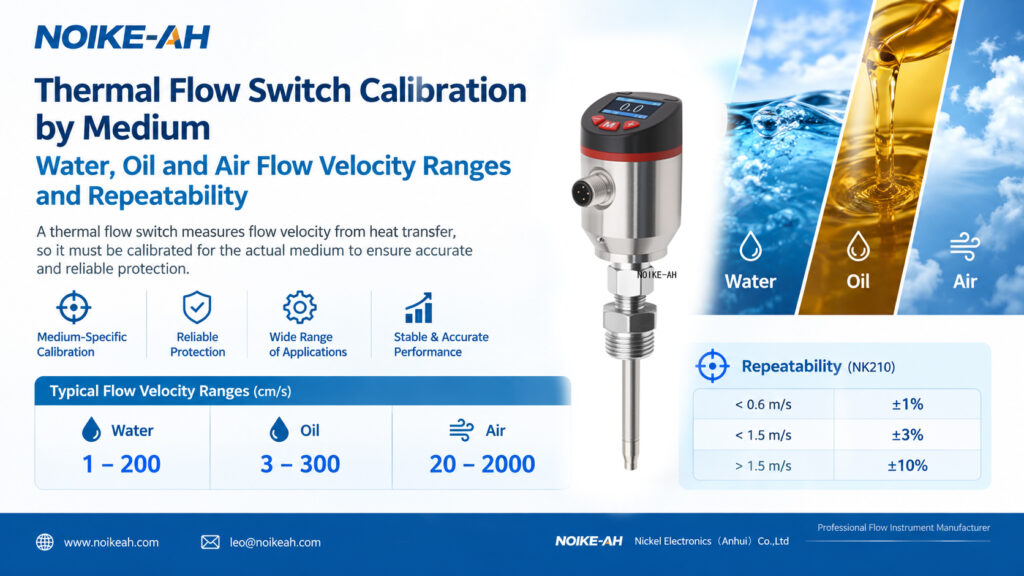
For the NOIKE-AH NK210, the published flow velocity ranges are 1–200 cm/s for water, 3–300 cm/s for oil and 20–2000 cm/s for air. Its published repeatability also varies with flow velocity. Correct medium selection, probe installation and switching-point verification are therefore essential for reliable low-flow monitoring and equipment protection.
Key Takeaways
- Calibration depends on the medium: Water, oil and air produce different thermal responses at the same flow velocity.
- Verify the model-specific range: The NK210 covers water at 1–200 cm/s, oil at 3–300 cm/s and air at 20–2000 cm/s.
- Repeatability varies with velocity: The NK210 specifies ±1% below 0.6 m/s, ±3% below 1.5 m/s and ±10% above 1.5 m/s.
- Installation affects the result: Probe immersion, pipe diameter, orientation and flow disturbances can influence the thermal signal.
- A flow switch is not a flow meter: It indicates whether flow is above or below a configured switching threshold rather than providing a continuous calibrated flow-rate reading.
1. What Is Thermal Flow Switch Calibration?
Thermal flow switch calibration is the process of establishing or verifying the sensor’s response and switching threshold under specified medium and operating conditions.
A thermal dispersion flow switch typically uses two sensing elements:
- Heated sensing element: Its temperature changes as flowing fluid carries heat away.
- Reference element: It provides a temperature reference for evaluating the thermal response.
The electronics interpret the temperature difference or related thermal signal and determine whether the flow condition meets the configured switching threshold.
Calibration helps establish a reliable relationship between the sensor’s thermal response and the required flow condition. The appropriate procedure depends on the model, medium, operating temperature and manufacturer’s instructions.
2. Why Does Calibration Depend on Water, Oil and Air?
Thermal flow switches rely on heat transfer, and different media have different thermal and physical properties. As a result, the same flow velocity does not necessarily produce the same sensor response.
Important factors include:
| Factor | Effect on Thermal Response |
|---|---|
| Thermal conductivity | Influences how efficiently heat transfers from the probe into the medium. |
| Specific heat capacity | Affects how much energy the medium absorbs as its temperature changes. |
| Density | Influences the mass of medium passing the sensing element at a given velocity. |
| Viscosity | Affects the flow boundary layer around the probe and can influence heat transfer. |
| Medium temperature | Changes the thermal conditions and may affect the sensor’s baseline response. |
Water
Water generally provides an effective cooling response at the sensing probe. Thermal flow switches are commonly used for cooling-water monitoring, circulation checks and pump protection.
The actual switching point should still be verified under the intended installation and operating conditions.
Oil
Oil performance depends on the oil type, viscosity and operating temperature. More viscous oils can produce a different thermal response from water, even when the flow velocity is similar.
Before selecting a switching threshold, confirm the oil grade, expected viscosity and operating temperature.
Air
Air transfers heat differently from liquids. A thermal flow switch intended for liquid service should not automatically be assumed suitable for air monitoring.
Verify the model’s specified gas range and calibration procedure before selecting a device for pneumatic systems or compressed-air monitoring.
3. Thermal Flow Switch Velocity Ranges for Water, Oil and Air
Published velocity ranges vary by manufacturer and model. The following table summarizes the ranges stated in the source specifications for the NOIKE-AH NK210 and selected manufacturer references.
| Medium | NOIKE-AH NK210 Flow Velocity Range |
|---|---|
| Water | 1–200 cm/s |
| Oil | 3–300 cm/s |
| Air | 20–2000 cm/s |
Unit conversion: 100 cm/s = 1 m/s.
These values describe the stated sensor velocity ranges, not recommended operating velocities for every pipe or application. Actual performance depends on the installation, flow profile, medium properties and calibration conditions.

How to Apply These Ranges
- Water applications: Check whether the minimum flow requiring detection falls within the model’s usable range.
- Oil applications: Confirm the oil’s viscosity and temperature rather than relying on the water range.
- Air applications: Verify that the specified gas range covers the actual operating conditions.
- All applications: Confirm the switching-point adjustment range and medium-specific requirements in the current datasheet.
Do not treat the maximum range value as a recommended alarm set point. The threshold should be based on the process’s actual minimum acceptable flow condition.
4. How Does Repeatability Change with Flow Velocity?
Repeatability describes how consistently a sensor produces the same result when tested repeatedly under the same conditions. It is different from accuracy and should not be used as a substitute for an accuracy specification.
The published NK210 repeatability values are:
| Flow Velocity | Published Repeatability |
|---|---|
| Below 0.6 m/s | ±1% |
| Below 1.5 m/s | ±3% |
| Above 1.5 m/s | ±10% |
These figures should be interpreted according to the manufacturer’s specification and test conditions. The published bands overlap as written, so confirm the applicable boundaries and calculation basis with the manufacturer before using them for acceptance testing or engineering calculations.
For comparison, the source material states that the KOBOLD KAL specifies ±2% repeatability for its water-based applications. This is a model-specific figure and should not be treated as a universal specification for thermal flow switches.
Why Repeatability Matters
A flow switch is often used to trigger an alarm or control action when flow drops below a required threshold. If the selected switching point is unsuitable for the operating range, changes in the thermal signal may affect switching consistency.
For pump dry-run protection, for example, establish the minimum flow required by the equipment and verify that the switch responds appropriately around that condition. Do not choose a threshold solely as a percentage of the sensor’s maximum range.
5. How to Calibrate a Thermal Flow Switch
The exact procedure depends on the device’s design and manufacturer instructions. Where field teaching or calibration is supported, the following workflow provides a practical starting point.
Step 1: Confirm the Actual Medium
Identify whether the application uses water, oil, air or another medium. For oil, record the expected viscosity and operating temperature. For gas service, confirm that the model supports the specific application.
Step 2: Check the Installation
Verify the process connection, insertion depth, probe orientation and immersion requirements. For liquid applications, confirm that the probe is installed as specified and that the pipe remains full during measurement.
Avoid installation locations where bends, valves, pumps or other disturbances create a flow profile that is unsuitable for the sensor.
Step 3: Establish a Representative Normal-Flow Condition
Operate the system at a known, representative flow condition. Follow the manufacturer’s instructions to establish the reference response or perform the applicable teaching procedure.
Do not assume that a calibration performed in one medium can be transferred directly to another.
Step 4: Verify the Low-Flow or No-Flow Condition
Where supported, follow the manufacturer’s procedure for establishing a low-flow or no-flow reference. Confirm that the process condition used for teaching is appropriate for the intended application.
Step 5: Set the Switching Threshold
Adjust the switching point according to the required process condition and the device’s available settings.
For pump protection, the threshold should reflect the minimum acceptable flow required by the pump or system. It should not be selected arbitrarily.
Step 6: Test the Switching Response
Increase or decrease the flow around the configured threshold and confirm that the output changes as intended. Verify the connected controller, relay or PLC input where applicable.
Record the medium, operating temperature, test conditions, switching point and observed response so the setup can be checked later.
Important: Field calibration is not automatically required for every installation. If the factory calibration and switching threshold already suit the actual medium and application, additional teaching may not be necessary. Follow the model-specific instructions.

6. Installation Factors That Affect Thermal Flow Switch Performance
Even a correctly selected sensor can produce an unsuitable response if the installation differs significantly from the intended conditions.
Probe Insertion Depth
Insufficient immersion can expose the sensing area to conditions that do not represent the main flow. Follow the specified insertion requirements.
Pipe Diameter and Flow Profile
Velocity distribution varies across a pipe. Nearby elbows, reducers, valves and pumps can disturb the flow profile and influence the sensor’s thermal response.
Medium and Operating Temperature
Changes in oil viscosity or medium temperature can alter heat transfer. Confirm whether the application requires a new calibration or a revised switching point when operating conditions change.
Switching Response Time
The NK210 source specifications state a response time of 1–13 seconds, typically 2 seconds, and an initialization time of approximately 8 seconds.
Consider these values when designing low-flow alarms or equipment-protection logic. Verify the required response time against the actual hazard and control-system requirements.
7. NOIKE-AH NK210 Integrated Flow & Temperature Sensor
The NOIKE-AH NK210 Standard Series is an integrated flow and temperature sensor using the thermal dispersion principle. According to the supplied product specifications, its main parameters include:
| Parameter | NK210 Specification |
|---|---|
| Water velocity range | 1–200 cm/s |
| Oil velocity range | 3–300 cm/s |
| Air velocity range | 20–2000 cm/s |
| Repeatability | ±1% below 0.6 m/s; ±3% below 1.5 m/s; ±10% above 1.5 m/s |
| Outputs | PNP / NPN / relay; NO / NC configurable |
| Load capacity | 500 mA for 24 VDC PNP/NPN; 60 W for relay |
| Display | 0.96-inch OLED showing flow, trend and switch status |
| Setting method | Keypad adjustment |
| Pressure rating | 100 bar; 300 bar optional |
| Response time | 1–13 seconds, typically 2 seconds |
| Initialization time | Approximately 8 seconds |
| Power supply | 24 VDC ±20% |
| Protection | IP67; reverse-polarity, short-circuit and overload protection |
| Medium temperature | -20°C to +85°C |
| Ambient temperature | -40°C to +85°C |
| Wetted materials | 304 stainless steel probe and housing |
| Connection | M12 connector or 2 m cable (default) |
Potential applications include pneumatic and hydraulic systems, cooling-water monitoring, cutting-fluid circulation, lubricating-oil monitoring and pump dry-run protection.
Before ordering, confirm the medium, switching threshold, process connection, operating conditions and required output configuration with the manufacturer. Check the latest datasheet for the exact model and configuration.
Product page: Integrated Flow & Temperature Sensor NK210
8. Frequently Asked Questions
Why does a thermal flow switch need medium-specific calibration?
A thermal flow switch detects flow through heat transfer. Water, oil and air have different thermal properties, so the sensor response at a given velocity can differ between media. Calibration and switching-point verification should match the actual application.
What are the water, oil and air velocity ranges of the NK210?
The stated NK210 ranges are 1–200 cm/s for water, 3–300 cm/s for oil and 20–2000 cm/s for air. Confirm the current datasheet and applicable calibration conditions before selection.
Does every thermal flow switch require field calibration?
No. Additional field teaching may not be necessary when the factory calibration and switching threshold already suit the actual medium and operating conditions. Follow the manufacturer’s instructions.
Is a thermal flow switch the same as a flow meter?
No. A flow switch indicates whether flow is above or below a configured threshold. A flow meter is used to measure flow rate, with its measurement output and performance defined by its specifications.
Does repeatability mean accuracy?
No. Repeatability describes the consistency of repeated results under the same conditions. Accuracy describes how closely a measurement agrees with the true or reference value. They are different performance characteristics.
What should be checked before setting a low-flow alarm?
Confirm the minimum acceptable process flow, medium, operating temperature, installation, switching adjustment range and response time. Test the output around the intended threshold under representative operating conditions.
9. Conclusion
Reliable thermal flow switch operation depends on matching calibration to the actual medium and installation. Water, oil and air produce different thermal responses, while repeatability and switching behavior can vary with velocity.
For the NOIKE-AH NK210, verify the stated velocity range, repeatability band, switching threshold and response time against the process requirements. Correct installation and functional testing help establish whether the switch can reliably support low-flow monitoring and equipment protection.
Need Help Selecting a Thermal Flow Switch?
NOIKE-AH provides industrial flow, pressure, temperature and level sensing solutions. When selecting a thermal flow switch, share your medium, operating temperature, pipe size, required minimum flow velocity, working pressure and preferred output.
Contact: [email protected]
Website: https://www.noikeah.com/