Continuous Lubricating and Hydraulic Oil Flow Monitoring: Detect Filter Clogging, Pump Leakage and Oil Leaks
1. What Is Continuous Hydraulic Oil Flow Monitoring?
Continuous hydraulic oil flow monitoring uses a flow meter to measure and record flow rate over time, helping operators identify abnormal trends before they develop into more serious system problems.
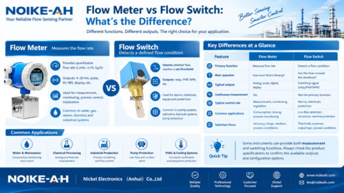
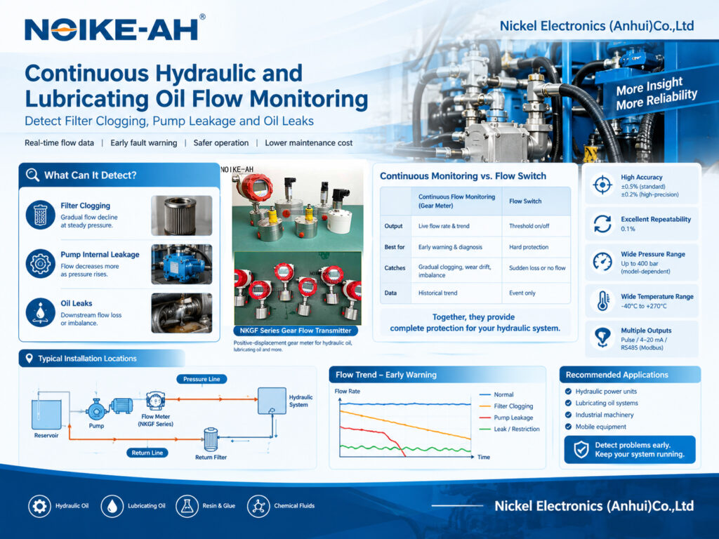
Unlike a flow switch, which triggers an alarm when flow crosses a predefined threshold, a continuous positive-displacement gear flow meter provides ongoing flow data. By comparing actual flow with a baseline recorded at the same operating pressure and oil temperature, operators can identify potential filter clogging, pump internal leakage, external leaks and flow restrictions.
In hydraulic power units and lubricating oil circuits, common flow patterns include:
- Gradual flow decline: May indicate increasing resistance caused by a clogged return-line filter.
- Flow decline as pressure increases: May indicate pump internal leakage or worn internal clearances.
- Downstream flow loss or imbalance: May indicate an external leak, a blocked valve or another restriction.
- Unstable flow: May indicate air entrainment, cavitation or pump pulsation.
Continuous flow monitoring supports predictive maintenance and fault diagnosis, while a flow switch provides threshold-based protection. Using both devices can improve fault detection and operational safety.
2. Key Definitions in Hydraulic and Lubricating Oil Flow Monitoring
Understanding the following terms helps establish an effective monitoring strategy.
Continuous flow monitoring: Measuring live flow rate and, where supported, accumulated volume over time to identify changes in operating conditions.
Flow switch protection: Using a threshold device to trigger an alarm or shutdown when flow falls below a specified set point. A conventional flow switch does not provide the same continuous trend data as a flow meter.
Pump internal leakage: Oil passing through internal pump clearances instead of being delivered to the hydraulic circuit. As pressure increases, internal leakage may increase and reduce effective output flow.
Return-line filter clogging: Contaminants accumulate in the filter element and increase flow resistance. A declining flow trend may provide an early indication of a developing restriction, depending on the system configuration.
Pressure-matched baseline: The normal flow rate recorded at a defined operating pressure and oil temperature. Subsequent measurements are compared with this reference to identify abnormal changes.

3. Where Should a Flow Meter Be Installed?
The appropriate measurement location depends on the fault being investigated. Measuring at different points in the circuit can help distinguish pump performance problems from downstream restrictions or leakage.
| Measurement Location | What It Helps Identify |
|---|---|
| Pump outlet or pressure line | Pump output changes with pressure, potential internal leakage and wear |
| Downstream of the return-line filter | Changes in flow associated with filter clogging, subject to circuit configuration |
| Main lubrication supply line | Oil delivery to bearings and gears, including potential low-flow interlock conditions |
| Segmented test points along the circuit | The section where flow is lost because of a leak or blockage |
For pump diagnosis, compare outlet flow with a pressure-matched baseline. For leak or blockage localization, measurements at selected downstream points can help narrow down the affected section.
The installation location must also be compatible with the circuit’s pressure rating, fluid temperature, flow range and operating conditions.
4. How to Identify Common Hydraulic System Faults from Flow Trends
Continuous flow data becomes more useful when changes in flow are interpreted alongside operating pressure, oil temperature and other system conditions.
| Observed Flow Trend | Possible Cause | Recommended Check |
|---|---|---|
| Flow gradually decreases over several weeks at steady pressure | Return-line filter clogging | Inspect the filter element and verify the condition before bypass activation |
| Flow decreases more significantly as system pressure rises | Pump internal leakage or worn clearances | Compare pump output against the pressure-matched baseline |
| Downstream flow is lost and visible oil leakage is present | External leak or ruptured line | Inspect the circuit and use segmented measurements to locate the affected section |
| Flow is low but the pump sounds normal | Blocked valve, strainer or another restriction | Check valves, strainers and fittings sequentially |
| Flow fluctuates or becomes erratic | Air entrainment, cavitation or pump pulsation | Inspect the suction line, reservoir oil level and the need for pulsation damping |
These patterns are diagnostic indicators, not definitive proof of a particular fault. Confirm the suspected cause through inspection and additional measurements.
5. How to Establish a Flow Baseline and Configure Trend Alarms
A reliable monitoring strategy starts with a reference measurement and compares subsequent readings under comparable operating conditions.
Step 1: Record Normal Operating Conditions
During commissioning, record normal flow rates at several operating pressures and at a stable oil temperature. These measurements establish the reference conditions for future comparisons.
Step 2: Log Flow Continuously
Use a suitable output, such as 4–20 mA or RS485 (Modbus), to transmit flow data to a PLC or SCADA system where supported by the selected configuration.
Continuous logging provides a historical record that can reveal gradual changes not captured by a single threshold alarm.
Step 3: Configure Trend-Based Alarms
Set an alarm to identify a sustained decline from the established baseline, rather than relying exclusively on a low-flow trip point.
The alarm threshold should be determined according to the equipment requirements, normal operating variability and the consequences of insufficient flow.
Step 4: Compare Readings at Matched Pressure and Temperature
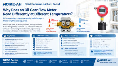
Oil viscosity changes with temperature, affecting flow behavior and potentially influencing measurement results. Compare readings at similar operating temperatures and pressures, or apply an appropriate correction where supported by the measurement method.
Step 5: Re-Establish the Baseline After Maintenance
After a filter replacement, oil change or pump service, verify the new normal operating condition and update the baseline when appropriate.
This helps prevent a legitimate change in system performance after maintenance from being misclassified as a developing fault.

6. Continuous Gear Flow Meter Monitoring vs. Flow Switch Protection
Continuous flow monitoring and flow switches serve different purposes in hydraulic and lubricating oil systems.
| Comparison | Continuous Gear Flow Meter | Flow Switch |
|---|---|---|
| Output | Live flow rate and historical trend data | Threshold-based flow status |
| Primary purpose | Early warning, predictive maintenance and fault diagnosis | Immediate threshold alarm or shutdown |
| Typical detection capability | Gradual clogging, performance drift and flow imbalance | Sudden flow loss or flow below a defined threshold |
| Historical data | Available when connected to a suitable logging system | Typically records an event only when integrated with an external monitoring system |
| Diagnostic value | Helps identify when and how flow changes | Indicates that a threshold condition has occurred |
Which is better for hydraulic oil monitoring?
A flow switch is suitable for straightforward threshold-based protection. A continuous gear flow meter is more suitable when operators need to observe flow trends and investigate developing problems.
The two devices complement each other: the switch provides threshold-based protection, while continuous monitoring supplies additional data for fault diagnosis and maintenance planning.
7. Limitations and Installation Considerations
Before selecting a flow meter for a hydraulic or lubricating oil circuit, consider the following factors.
Hydraulic Pressure Pulsation
Hydraulic systems may produce pulsating flow. Severe pulsation can affect measurement stability and may require signal filtering or a suitable pulsation damper. Confirm the appropriate approach with the flow meter supplier.
Oil Viscosity and Temperature
Oil viscosity changes with temperature. To avoid misleading comparisons, measure under matched temperature conditions or use an appropriate correction method supported by the measurement system.
Pressure Rating and Meter Configuration
A flow meter must be suitable for the circuit’s operating pressure, fluid temperature, flow range and installation conditions. Output options and communication interfaces also depend on the selected model.
This article describes a flow-monitoring method; it does not certify that a particular flow meter is suitable for every high-pressure or pulsating hydraulic circuit. Confirm the required pressure rating, output configuration and mounting arrangement with the supplier before ordering.
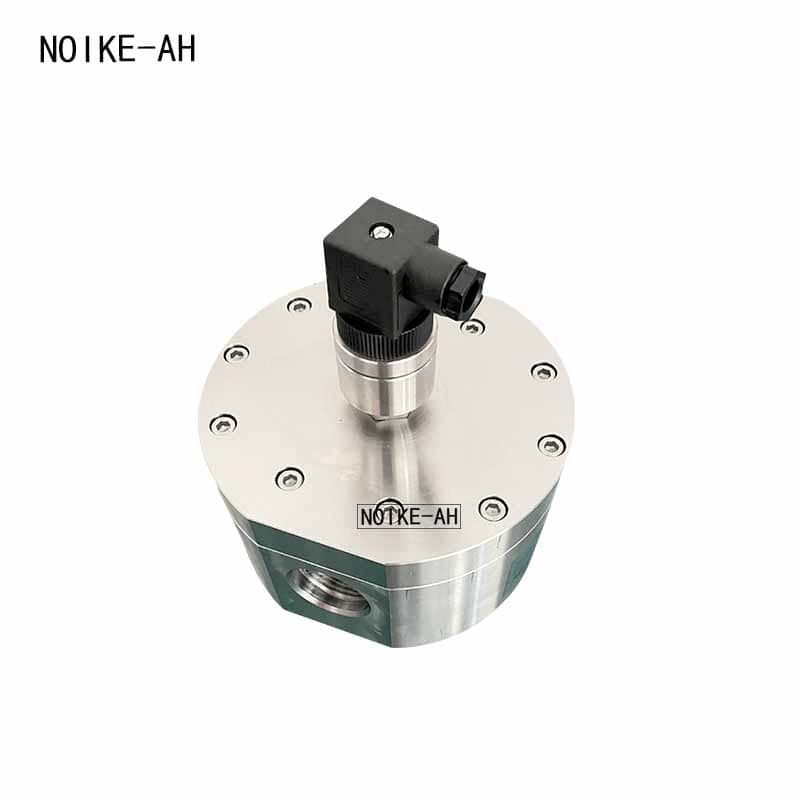
8. Recommended Product: NOIKE-AH NKGF Series Gear Flow Transmitter
The NOIKE-AH NKGF Series Gear Flow Transmitter is a positive-displacement gear flow meter listed for measuring lubricating oil, hydraulic oil, resin, glue and chemical fluids.
Depending on the selected configuration, its output options include Pulse, 4–20 mA and RS485 (Modbus), supporting continuous flow monitoring, data transmission and trend logging when integrated with a compatible system.
Published Product Specifications
| Parameter | Published Specification |
|---|---|
| Measurement principle | Positive-displacement gear flow measurement |
| Accuracy | ±0.5% standard / ±0.2% high-precision |
| Repeatability | 0.1% |
| Maximum pressure | Up to 400 bar, depending on model |
| Fluid temperature range | -40°C to +270°C |
| Output options | Pulse / 4–20 mA / RS485 (Modbus) |
These specifications are based on the published product information. Actual performance and compatibility depend on the selected model and operating conditions.
For hydraulic power units and lubricating oil circuits, confirm the required flow range, operating pressure, oil temperature, output type and pulsation conditions before selecting a configuration.
Product details: NOIKE-AH Gear Flow Transmitter NKGF Series
9. Frequently Asked Questions About Hydraulic Oil Flow Monitoring
Should I use a flow switch or a flow meter for hydraulic monitoring?
Use a flow switch for threshold-based protection and a continuous flow meter for trend-based early warning and diagnosis. The two devices can be used together to provide complementary monitoring functions.
How can a clogged filter be detected through flow monitoring?
A clogged filter may cause a gradual change in flow as resistance increases. Comparing measurements under consistent operating conditions can help identify this trend. The actual response depends on the circuit design, filter location and pressure conditions.
How can I detect pump internal leakage using a flow meter?
Record pump output at several operating pressures and establish a baseline. If output flow declines as pressure rises, internal leakage or worn clearances may be contributing. Additional checks are required to confirm the cause.
Where should I install a flow meter to locate an oil leak?
Start by measuring flow at the pump outlet, then compare measurements at selected downstream points. Segmented measurements can help identify where flow is lost. Installation must be suitable for the circuit’s pressure and operating conditions.
Why should flow readings be compared at the same oil temperature?
Oil viscosity generally decreases as temperature rises, which changes flow behavior and may affect measurement results. Comparing readings at similar temperatures improves the reliability of trend analysis.
Can a gear flow meter replace a hydraulic flow switch?
Not necessarily. A flow meter provides measurement data, while a flow switch provides a defined threshold response. Whether one device can replace the other depends on the protection requirements, system design and control configuration.
10. Related Reading
For additional information about flow meter selection and high-viscosity fluid measurement, see:
- How to Choose a Flow Meter for High-Viscosity Liquids
- Measuring High-Viscosity Fluids: Why Gear Flow Meters Are Essential
- Gear Flowmeter Selection Guide
- Gear Flow Transmitter NKGF Series
- JVH high-pressure positive-displacement gear flow meter for hydraulic power units.
Conclusion
Continuous hydraulic and lubricating oil flow monitoring provides more diagnostic information than a single threshold signal. By recording flow over time and comparing measurements at matched pressure and temperature, operators can identify potential filter clogging, pump internal leakage, external leaks and flow restrictions earlier.
For applications requiring continuous flow data and integration with PLC or SCADA systems, the NOIKE-AH NKGF Series Gear Flow Transmitter offers configurable output options for monitoring and logging. Confirm the model-specific operating limits and installation requirements before selecting a meter for a particular hydraulic or lubrication circuit.