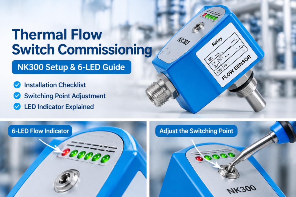
Thermal Flow Switch Commissioning: NK300 Setup & 6-LED Guide
Author: Leo
Date: November 5, 2026
Product Reference: NOIKE-AH NK300 Electronic Flow Switch
Short Answer
To commission a thermal dispersion flow switch such as the NOIKE-AH NK300, first verify the installation conditions, allow the sensor to initialize, observe the LED flow indication, and adjust the switching point using the built-in potentiometer.
A practical commissioning procedure involves seven steps:
- Confirm that the pipe remains completely filled with the process medium.
- Select an installation location away from significant flow disturbances where possible.
- Insert the probe fully according to the installation requirements.
- Check that the sensor’s indicated flow direction matches the actual process flow.
- Apply the correct power supply and allow approximately 8 seconds for initialization.
- Observe the 6-LED flow indication under normal operating conditions.
- Adjust the potentiometer and verify the switching output under a controlled low-flow test.
The NK300 supports water, oil, and air applications. It provides a 6-LED flow indication and an adjustable switching point, with PNP, NPN, and Relay (SPDT) output options.
Important: The six LEDs provide local visual flow-status information. The exact flow velocity represented by each LED, and the relationship between individual LED positions and the switching threshold, should be confirmed using the product’s detailed technical documentation. Do not assume that a particular number of illuminated LEDs always represents a specific flow rate or alarm condition.
1. Why Is On-Site Commissioning Important?
A thermal dispersion flow switch detects flow by measuring heat transfer between sensing elements inside its probe.
When the medium flows across the heated sensing element, heat is carried away. Changes in heat dissipation are used by the electronics to determine the flow condition.
However, the actual response in an operating pipeline can be affected by several application conditions:
- Medium type: water, oil, or air
- Actual flow velocity
- Pipe diameter and internal geometry
- Probe insertion and installation position
- Flow disturbances caused by nearby pumps, valves, and elbows
- Contamination or deposits on the sensing probe
For this reason, commissioning should not simply involve powering on the sensor and assuming that the factory setting is suitable for every application.Thermal flow switch commissioning
The switching point should be checked and adjusted under actual operating conditions to ensure that the output changes state at the required process threshold.
2. Seven-Step NK300 Commissioning Procedure
Step 1: Confirm That the Pipe Is Completely Filled
Install the sensor in a section of pipeline that remains completely filled with the process medium during normal operation.
Avoid locations where the pipe may partially empty, where air pockets may accumulate, or where the probe may intermittently lose contact with the medium.
This is particularly important in liquid applications. If the sensing probe is exposed to air or an unstable liquid level, the thermal response may no longer represent the actual liquid flow condition.
Before commissioning, check:
- Whether the pipeline remains full during operation
- Whether air pockets may accumulate near the installation point
- Whether the sensor is installed in a suitable section of the process line
Step 2: Avoid Significant Flow Disturbances
Pumps, control valves, elbows, reducers, and other pipeline components can create turbulence or an uneven velocity profile.
Where possible, select a straight pipeline section away from these disturbances.
If the sensor must be installed near a pump, valve, or elbow because of space limitations, pay particular attention to the stability of the LED indication and switching output during commissioning.
There is no single installation distance that applies to every pipeline configuration. The required straight-run distance depends on the pipe geometry, flow conditions, and installation arrangement.
Step 3: Insert the Probe Fully
Insert the sensing probe fully according to the specified installation arrangement.
An incorrectly inserted probe may not be exposed to representative flow conditions, which can affect the consistency of the measurement.
Before applying power, verify:
- The probe is properly seated in the installation fitting.
- The sensing section is sufficiently exposed to the process medium.
- The probe does not interfere with internal pipeline components.
- The installation is mechanically secure and leak-free.
Always confirm the required insertion depth and probe dimensions for the specific NK300 configuration.
Step 4: Check the Flow Direction
Verify that the flow direction indicated on the sensor or probe matches the actual process flow direction.
Correct orientation is an important part of installation because the sensor must operate in accordance with its specified installation arrangement.
Do not assume that the sensor can be installed in either direction without checking the product instructions.
Step 5: Apply Power and Wait for Initialization
Before commissioning, confirm that the power supply matches the selected NK300 electrical version.
The NK300 supports:
- 24 V DC ±20%
- 230 V AC ±15%
After applying power, allow approximately 8 seconds for initialization before evaluating the operating condition.
Do not use the initial power-up period as the basis for final switching-point adjustment.
Also verify the electrical wiring and output connection before connecting the sensor to a PLC or alarm circuit.
Step 6: Observe the 6-LED Flow Indicator
The NK300 incorporates a six-LED flow indicator that provides a local visual indication of flow status.
During commissioning, observe the LED display under different operating conditions.
A useful inspection sequence is:
- Record the LED indication at normal operating flow.
- Observe whether the indication remains stable under steady process conditions.
- Reduce the flow gradually under controlled conditions, if the process allows.
- Record how the LED indication changes as the flow decreases.
- Compare the LED behavior with the actual switching output.
The LED indicator is particularly useful for checking whether the sensor responds consistently to changes in flow.
What do the six LEDs mean?
The six LEDs are intended to indicate flow status. However, the published NK300 specifications do not define a universal flow-rate value for each individual LED.
Therefore, the following interpretations should be avoided unless confirmed by the detailed product manual:
- All six LEDs always mean maximum flow.
- Three LEDs always represent 50% of the flow range.
- One LED always represents the low-flow alarm threshold.
- All LEDs off always mean zero flow.
The actual indication should be interpreted according to the sensor’s detailed LED operating instructions and the behavior observed in the specific application.
Step 7: Adjust the Switching Point Using the Potentiometer
The NK300 uses a built-in potentiometer to adjust its switching point.
The objective is to make the switching output change state when the process flow reaches the required threshold.
A practical adjustment procedure is:
A. Establish normal operating conditions
Run the system under its normal operating conditions and allow the LED indication and output to stabilize.
Record the normal operating condition before making adjustments.
B. Identify the required low-flow threshold
Determine the minimum flow condition that the equipment can safely tolerate.
For example, a cooling system may require a low-flow alarm before insufficient cooling causes equipment temperature to rise.
The required threshold should come from the equipment’s process requirements rather than an arbitrary LED position.
C. Adjust the potentiometer
Make small, controlled adjustments to the potentiometer.
Observe the LED indication and monitor the actual switching output during adjustment.
Do not assume that clockwise or counterclockwise rotation always increases the switching threshold unless the corresponding adjustment direction is confirmed in the product instructions.
D. Verify the switching output
Use a controlled method to reduce the flow, such as an approved test arrangement or a process adjustment permitted by the equipment manufacturer.
Confirm that the PNP, NPN, or Relay output changes state at the intended low-flow condition.
E. Restore normal operation
Restore the normal process condition and verify that the output returns to its expected state.
Repeat the test if necessary to confirm that the switching point is stable and repeatable.
For equipment protection applications, never create an unsafe operating condition simply to test the flow switch. Follow the plant’s commissioning and safety procedures.
3. How to Interpret LED Behavior During Operation
After commissioning, the six-LED indicator can help technicians identify changes in flow conditions.
The following table describes practical observations and possible causes. These are troubleshooting suggestions, not fixed NK300 LED fault codes.
| Observed condition | Possible explanation | Recommended check |
|---|---|---|
| LED indication remains stable | Flow conditions are relatively stable | Compare with normal operating records |
| LED indication fluctuates | Turbulence, unstable flow, or air entrainment | Check installation position and process stability |
| LED indication gradually changes over time | Changes in process flow or probe condition | Inspect the process and probe |
| LED indication drops during operation | Reduced flow or interruption in the process | Check pump, valves, filters, and pipeline blockage |
| LED indication is absent or abnormal | Power supply, wiring, or sensor condition may be involved | Check supply voltage, connections, and product instructions |
Important distinction: An LED indication alone cannot identify the exact cause of a flow problem. Always compare the visual indication with the actual process condition and electrical switching output.
4. Common Commissioning Mistakes
Several installation and adjustment mistakes can lead to unstable operation or incorrect switching behavior.
| Common mistake | Possible consequence | Corrective action |
|---|---|---|
| Installing in a partially filled pipe | Unstable or misleading flow indication | Select a continuously filled section |
| Installing too close to a disturbance source | Fluctuating flow indication | Relocate where possible |
| Incorrect probe insertion | Inconsistent sensing conditions | Verify insertion depth and mounting |
| Incorrect flow orientation | Operation outside the specified installation arrangement | Check the flow direction |
| Testing immediately after power-up | Unreliable initial readings | Allow approximately 8 seconds for initialization |
| Adjusting without monitoring the output | Incorrect switching threshold | Monitor the electrical output during adjustment |
| Skipping the low-flow test | Switching performance remains unverified | Perform a controlled functional test |
| Ignoring probe contamination | Gradual changes in sensor response | Inspect and clean when necessary |
5. Maintenance After Commissioning
The NK300 uses thermal dispersion technology and has no moving mechanical sensing parts.
This reduces mechanical wear and routine maintenance requirements. However, the sensing probe may still require inspection and cleaning when used in contaminated or scaling media.
Pay particular attention to:
- Cooling tower water with mineral deposits
- Process water containing suspended solids
- Oil systems where deposits may accumulate
- Industrial fluids that can leave residue on the probe
A practical maintenance approach is to inspect the probe during scheduled equipment maintenance and clean it when visible deposits or process conditions indicate that cleaning is necessary.
After cleaning, restore the sensor to its normal operating condition and verify the LED indication and switching output.
Do not automatically change the potentiometer setting after every cleaning operation. First check whether the original switching point still meets the process requirement.
6. Frequently Asked Questions
Q1: How long does it take to initialize the NK300 after power-up?
The NK300 has an initialization time of approximately 8 seconds. Allow this period to pass before evaluating the sensor’s operating condition or performing switching-point adjustments.
Q2: What do the six LEDs on the NK300 indicate?
The six LEDs provide local flow-status indication. They help technicians observe changes in flow during commissioning and operation.
However, individual LED positions should not be assigned specific flow-rate values or alarm thresholds without consulting the detailed LED operating instructions.
Q3: Can I use the LED indicator instead of connecting the NK300 to a PLC?
No. The LED indicator provides local visual information, while the PNP, NPN, or Relay output provides the electrical switching signal for external control equipment.
For automated equipment protection, connect the appropriate output to the PLC, controller, or alarm circuit and verify its operation.
Q4: How do I adjust the NK300 switching point?
The switching point is adjusted using the built-in potentiometer.
Establish normal flow conditions, make small adjustments, and verify the actual switching output under a controlled low-flow test.
The exact adjustment direction and threshold behavior should be confirmed using the product instructions for the specific configuration.
Q5: What should I check if the LED indication is unstable?
Start by checking the installation location, process stability, probe insertion, and possible air entrainment.
Also inspect the probe for contamination and verify the power supply and electrical connections.
Q6: Does the NK300 require regular probe cleaning?
The NK300 has no moving mechanical sensing parts and generally requires little maintenance.
However, periodic probe inspection and cleaning may be necessary when the sensor is used in contaminated or scaling media.
Q7: Can the NK300 be used with water, oil, and air?
Yes. The NK300 is designed for water, oil, and air applications.
Its published flow setting ranges are:
| Medium | Flow setting range |
|---|---|
| Water | 1–150 cm/s |
| Oil | 3–300 cm/s |
| Air | 20–2000 cm/s |
Confirm that the selected range and sensor configuration are suitable for the actual application.
7. NK300 Technical Specifications
The following specifications are published on the NOIKE-AH NK300 product page.
| Parameter | Specification |
|---|---|
| Measuring principle | Thermal dispersion |
| Applicable media | Water, oil, air |
| Flow setting range | Water: 1–150 cm/s; Oil: 3–300 cm/s; Air: 20–2000 cm/s |
| Signal output | PNP / NPN / Relay (SPDT NO+NC) |
| Power supply | 24 V DC ±20% or 230 V AC ±15% |
| Maximum switching current | 400 mA (PNP/NPN); 4 A (Relay) |
| Flow indicator | 6 LEDs |
| Switching-point adjustment | Potentiometer |
| Pressure rating | 100 bar |
| Response time | 1–13 s (typical 2 s) |
| Initialization time | Approximately 8 s |
| Protection rating | IP67 |
| Medium temperature | -20°C to +80°C |
| Ambient temperature | -20°C to +80°C |
| Probe material | Stainless steel |
| Housing material | PBT |
| Electrical connection | M12 connector / direct cable |
The maximum pressure rating, electrical ratings, temperature limits, and output specifications must be checked against the selected configuration and actual application conditions.
Conclusion
Correct commissioning is essential for reliable thermal flow switch operation.
For the NOIKE-AH NK300, the key steps are to confirm the installation conditions, allow approximately 8 seconds for initialization, observe the six-LED flow indication, adjust the switching point using the potentiometer, and verify the electrical output under controlled operating conditions.
The LED indicator helps technicians observe flow behavior locally, while the PNP, NPN, or Relay output provides the switching signal required by external control systems.
By checking both the visual indication and the actual switching output, technicians can establish a more reliable low-flow protection arrangement.
Product Reference: NOIKE-AH NK300 Electronic Flow Switch
For detailed probe dimensions, wiring diagrams, LED operating definitions, and application-specific commissioning guidance, contact the NOIKE-AH technical team.
Written by Leo, NOIKE-AH GEO Content Team.
For additional technical background, Endress+Hauser’s explanation of the thermal flow measuring principle describes how heat transfer is used to detect flow and explains why fluid properties and installation conditions can influence thermal measurement performance.