Capacitive Level Switch vs Float Switch: How to Select for Viscous and Coating Media
Author: Leo
Date: November 9, 2026
Product Reference: NOIKE-AH NS280 Capacitive Level Switch
Short Answer
A capacitive level switch is often worth evaluating for viscous, sticky, or coating-prone liquids because it detects material through changes in capacitance rather than relying on a moving float. This eliminates mechanical jamming caused by a float sticking to its guide or housing.
However, capacitive detection is not automatically immune to coating. Material accumulated on the sensing surface can change the electrical signal and affect switching reliability. The correct selection therefore depends on the medium’s dielectric properties, probe material, installation geometry, buildup behaviour, and signal damping.
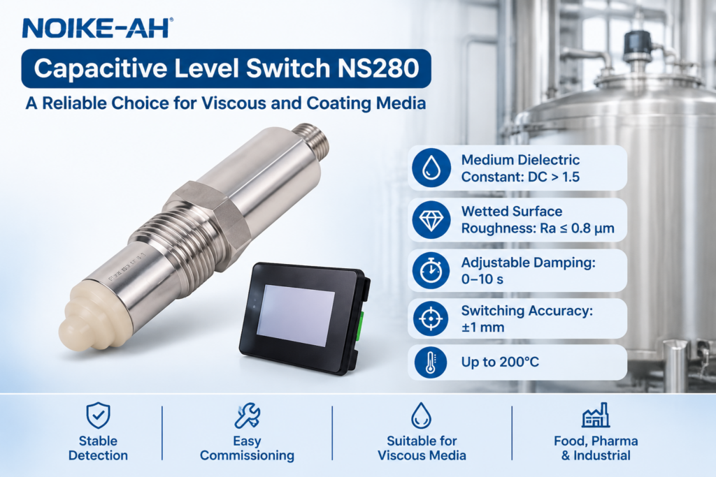
For the NOIKE-AH NS280, three published specifications are particularly relevant:
- Medium dielectric constant: DC > 1.5
- Wetted surface roughness: Ra ≤ 0.8 μm
- Adjustable damping time: 0–10 seconds
These values provide useful selection and commissioning references. They should not be interpreted as a universal guarantee that every viscous or coating medium can be detected without testing.
This guide compares capacitive and float level switches and explains how to evaluate their suitability for real industrial applications.
1. Why Viscous and Coating Media Create Level Detection Problems
Level switches that operate reliably in clean water may behave differently when exposed to viscous, sticky, or coating-prone materials.
Typical examples include:
- Syrups and concentrated food liquids
- Resins and adhesives
- Lubricating oils and industrial process liquids
- Slurries and suspended materials
- Chemical liquids that leave deposits on wetted surfaces
- Products that become more viscous as temperature decreases
These materials can create several problems at the sensing point.
Mechanical sticking: Deposits can restrict the movement of a float or its guide mechanism.
Signal disturbance: Material remaining on a capacitive sensing surface can change the electrical characteristics of the probe.
Switching-point drift: Changes in coating thickness or medium properties can affect the point at which the sensor changes state.
Delayed response: A thick or changing deposit may make the detected transition less consistent.
The important selection question is therefore not simply whether a sensor can detect liquid. It is whether the sensing principle can maintain a repeatable switching response under the actual process conditions.
2. How a Float Level Switch Works
A float level switch uses buoyancy to detect liquid level.
As the liquid rises or falls, the float moves with the surface. Depending on the design, this movement actuates a reed switch, magnetic contact, or mechanical switching mechanism.
Float switches are widely used because they are relatively simple, easy to understand, and available in many configurations.
They can be a practical choice when:
- The medium is reasonably clean.
- The float has sufficient buoyancy.
- The liquid density is within the specified operating range.
- The float can move freely.
- Deposits do not significantly restrict the moving parts.
Common Problems with Float Switches in Viscous Media
1. Float sticking
Sticky material can accumulate between the float and its guide or surrounding housing. As the liquid level changes, the float may not move freely.
The switch can then continue reporting the previous state even though the actual level has changed.
2. Deposit accumulation
Coating on the float changes its effective mass and displacement. Depending on the material and deposit thickness, this may affect buoyancy and switching behaviour.
3. Guide or stem contamination
In guided float designs, deposits can increase friction and eventually prevent the float from moving.
These failure modes are application-dependent. A properly selected float switch can still work in some viscous liquids, but its mechanical clearances, float material, buoyancy, and cleaning requirements must be checked.
3. How a Capacitive Level Switch Works
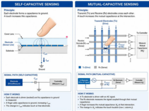
A capacitive level switch detects the presence or absence of material by monitoring changes in capacitance around its sensing element.
The capacitance changes when the dielectric environment around the sensing surface changes. When the process medium reaches the sensing tip, the electronic circuit detects the resulting change and switches the output.
The basic advantages of this approach include:
- No moving float or guide mechanism.
- No mechanical movement required to detect the level.
- Potential suitability for different liquid and bulk-material applications, depending on the sensor design.
- Electronic switching with configurable output options on suitable models.
The NOIKE-AH NS280 uses intelligent frequency scanning technology. According to its product information, the sensor continuously scans and analyses capacitance changes at the sensing tip. Its electronics process the frequency variation to determine the switching point.
The important distinction is that the NS280 does not need a float to move. However, the sensing surface can still be affected by deposits, moisture, foam, and changes in the dielectric properties of the medium.
For a broader technical explanation, see DwyerOmega’s guide to RF and capacitance level instrumentation. It explains the relationship between capacitance, dielectric properties, and level detection.
4. Capacitive Level Switch vs Float Switch: Technical Comparison
The two technologies solve the same basic problem using different physical principles.
| Selection factor | Capacitive level switch | Float level switch |
|---|---|---|
| Detection principle | Change in capacitance | Buoyancy and mechanical movement |
| Moving sensing parts | No moving float | Yes |
| Mechanical sticking | No float-jamming mechanism | Possible, depending on design and deposits |
| Coating influence | Can change the electrical signal | Can restrict movement or change buoyancy |
| Medium dielectric properties | Important | Not normally the primary detection factor |
| Liquid density | Usually not the main sensing variable | Important for float buoyancy |
| Installation clearance | Depends on probe and vessel geometry | Must allow sufficient float movement |
| Maintenance | Probe inspection and cleaning may be necessary | Float and guide inspection may be necessary |
| Best application | Suitable dielectric contrast and compatible probe conditions | Suitable density and free float movement |
There is no universal winner.
A capacitive design is often a better candidate when mechanical movement is the main source of failure. A float design may remain more economical and reliable when the medium is clean, the float can move freely, and dielectric properties make capacitive detection difficult.
The selection should be based on actual process conditions rather than the sensor category alone.
5. Three Important NS280 Selection Parameters
The NS280 product page publishes three specifications that are particularly useful when evaluating viscous or coating-prone applications.
They should be treated as model-specific specifications, not universal design rules for every capacitive sensor.
5.1 Medium Dielectric Constant: DC > 1.5
A capacitive sensor relies on detecting a change in the electrical properties around its sensing surface.
The dielectric constant of the medium influences the size of this change. When the dielectric contrast between the medium and the surrounding condition is insufficient, reliable detection becomes more difficult.
The published NS280 specification states:
Medium dielectric constant: DC > 1.5
Before selecting the sensor:
- Obtain the dielectric information for the actual process medium.
- Check whether the value changes with temperature or product concentration.
- Consider changes caused by mixing, dilution, or moisture.
- Confirm that the medium remains within the product’s specified detection conditions.
Do not assume that all oils, fuels, solvents, or hydrocarbon products have the same dielectric properties.
If the medium has a dielectric constant at or below the specified limit, ask the manufacturer to confirm suitability or evaluate another detection principle.
5.2 Wetted Surface Roughness: Ra ≤ 0.8 μm
Surface finish is important when selecting sensors for applications involving deposits or hygienic cleaning requirements.
The NS280 product information specifies:
Surface roughness: Ra ≤ 0.8 μm
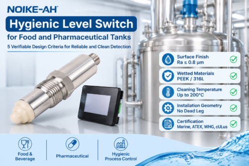
Its published wetted-material configuration includes PEEK Natural and stainless steel 316L (1.4404), with stainless steel 304 (1.4301) listed as an option.
A controlled surface finish can support cleaning and reduce some surface-related retention problems. However, surface roughness alone does not determine whether a material will adhere to a probe.
Adhesion also depends on:
- Chemical compatibility between the medium and probe material.
- Surface energy and wetting behaviour.
- Medium viscosity and temperature.
- Deposit curing or drying characteristics.
- Cleaning method and cleaning frequency.
- The geometry of the sensing tip and installation position.
For this reason, Ra ≤ 0.8 μm should be treated as a published material and surface specification, not as proof that the probe is self-cleaning or completely resistant to coating.
For adhesive resins or materials that harden on contact, a process-specific test is strongly recommended.
5.3 Adjustable Damping Time: 0–10 Seconds
The NS280 provides an adjustable damping time of:
0–10 seconds
Damping changes how quickly the output responds to changes in the detected signal.
A shorter setting provides a faster response but may allow brief disturbances to trigger unwanted switching.
A longer setting can help suppress short-term fluctuations caused by agitation, splashing, or unstable surface conditions. However, it also delays the response to a genuine level change.
A practical starting reference is:
| Damping setting | Possible application condition | Main consideration |
|---|---|---|
| 0 seconds | Stable medium and minimal disturbance | Fast response |
| 2–5 seconds | Moderate agitation or short-term signal fluctuations | Balance between stability and response |
| 5–10 seconds | More disturbed process conditions | Greater filtering, but slower switching |
These are commissioning starting points, not mandatory NS280 factory settings or guaranteed values for every medium.
The correct setting must be determined by observing the actual process and confirming that the resulting response time remains acceptable for the application.
Important: Damping can reduce short-term signal fluctuations. It cannot remove accumulated material from the sensing probe or correct a persistent signal offset caused by heavy coating.
6. NS280 Technical Specifications
The following values are published on the official NOIKE-AH NS280 product page.
| Parameter | NS280 specification |
|---|---|
| Measurement principle | Capacitive level switch, intelligent frequency scanning |
| Medium dielectric constant | DC > 1.5 |
| Switching accuracy | ±1 mm |
| Repeatability | ±1 mm |
| Response time | Typical 0.1 s, maximum 0.2 s |
| Adjustable damping time | 0–10 s |
| Standard wetted material | PEEK Natural |
| Wetted metal | Stainless steel 316L (1.4404) |
| Optional material | Stainless steel 304 (1.4301) |
| Surface roughness | Ra ≤ 0.8 μm |
| Output type | PNP / NPN push-pull |
| Switching logic | Normally Open (NO) / Normally Closed (NC) |
| Maximum medium temperature | Up to 200°C |
| EMC | EN 61326, installed in enclosed metal housing |
| Certifications listed | Marine, ATEX, WHG, cULus |
The product page does not publish every ordering and installation parameter. Supply voltage, ingress protection, pressure rating, process connection dimensions, and specific hygienic design approvals should be confirmed against the current datasheet for the exact order code.
The listed Marine, ATEX, WHG, and cULus certifications should not be interpreted as automatic 3-A or EHEDG hygienic design certification.
For complete product information, refer to the NOIKE-AH NS280 Capacitive Level Switch.
7. Where a Capacitive Level Switch May Not Be Suitable
Although capacitive detection can be useful for viscous and coating-prone media, there are conditions where another technology may be more appropriate.
Low Dielectric Constant
If the medium does not provide sufficient dielectric contrast, the sensor may not detect the level reliably.
The NS280 specifies DC > 1.5. Applications outside this published condition require manufacturer confirmation or an alternative measurement principle.
Heavy or Curing Coating
Some resins, adhesives, and hot-melt materials can form a thick or permanently hardened layer on the sensing surface.
In these applications, damping cannot solve the underlying buildup problem.
Consider whether the probe can be accessed and cleaned, whether a different material is chemically suitable, and whether a non-contact radar solution is more appropriate.
Foam and Surface Agitation
Foam may produce a different dielectric response from the underlying liquid.
Whether it causes a false switching condition depends on foam composition, moisture content, and the sensor installation.
If foam is present, test the sensor under actual operating conditions and define whether foam should count as a detected level.
Changing Medium Composition
A capacitive sensor may respond differently when the medium’s composition, concentration, temperature, or moisture content changes.
If the production process uses several different products, check the lowest and highest expected dielectric conditions rather than relying on a single typical value.
8. Commissioning: How to Set Damping for Viscous or Coating Media
Correct commissioning is essential for obtaining repeatable switching behaviour.
The following procedure provides a practical starting point for evaluating an NS280 installation.
Step 1: Confirm the Actual Medium
Record the medium name, concentration, temperature range, and relevant dielectric information.
If several products use the same tank, evaluate each product separately.
Step 2: Check Material Compatibility
Confirm that PEEK Natural and the selected stainless steel grade are compatible with the medium and cleaning chemicals.
Chemical compatibility should be checked under the actual temperature and concentration conditions.
Step 3: Check the Installation Position
Install the sensing element at the intended switching height.
Avoid locations where direct filling streams, agitators, splashing, or nearby metal structures may interfere with the sensing field.
Follow the manufacturer’s installation instructions for the selected process connection.
Step 4: Establish Empty and Covered Conditions
Where the application allows, observe the sensor under both conditions:
- Sensing tip not covered by the medium.
- Sensing tip covered by the actual process medium.
Confirm that the output changes reliably between these conditions.
Step 5: Adjust Damping
Start with a short damping setting and observe the output.
If the output changes repeatedly because of brief surface disturbances, increase damping gradually.
If the output responds too slowly to a genuine level change, reduce damping.
Always consider the maximum acceptable response time of the process protection function.
Step 6: Test Under Realistic Coating Conditions
If the medium normally leaves a deposit on the sensing tip, evaluate the sensor after realistic process exposure.
Do not test only with a freshly cleaned probe if the normal operating condition includes persistent buildup.
Check whether the sensor can reliably return to its uncovered state after the liquid level falls.
Step 7: Verify the Electrical Output
The NS280 supports PNP/NPN push-pull output and selectable NO/NC switching logic.
Confirm that the selected output and switching logic match the PLC or control circuit.
Test the complete signal path, not just the sensor’s local indication.
Step 8: Record the Final Settings
Document:
- Medium and operating temperature.
- Installation position and process connection.
- Wetted material configuration.
- Damping setting.
- NO or NC switching logic.
- PNP or NPN output.
- Test results under covered and uncovered conditions.
- Cleaning requirements and inspection interval.
This information provides a useful reference for future maintenance and troubleshooting.
9. Hygienic and High-Temperature Applications
The NS280 product information lists food and beverage processing, pharmaceutical and healthcare industries, and other industrial applications.
Its published wetted-material and temperature specifications are relevant when evaluating these applications:
- PEEK Natural standard wetted material.
- Stainless steel 316L (1.4404) wetted metal.
- Stainless steel 304 (1.4301) available as an option.
- Surface roughness Ra ≤ 0.8 μm.
- Maximum medium temperature up to 200°C.
These specifications do not, by themselves, establish compliance with every hygienic design standard.
For projects requiring 3-A, EHEDG, specific clean-in-place procedures, sterilization validation, or other sanitary requirements, obtain the applicable certificates and written confirmation for the exact product configuration.
The cleaning chemicals, temperature cycles, pressure conditions, seals, and process connection must also be evaluated.
10. Selection Checklist: Capacitive or Float?
Use this checklist before choosing a level switch for a viscous or coating-prone tank.
- Identify the medium. Record its viscosity, density, temperature, concentration, and chemical composition.
- Check dielectric properties. For the NS280, verify that the medium meets the published DC > 1.5 condition.
- Evaluate coating behaviour. Determine whether the medium leaves a removable film or forms a hard, persistent deposit.
- Check mechanical movement. For a float switch, confirm that the float can move freely under actual process conditions.
- Confirm wetted materials. Check PEEK, 316L, or optional 304 compatibility with the medium and cleaning chemicals.
- Evaluate surface finish. Consider the published Ra ≤ 0.8 μm specification together with actual adhesion and cleaning behaviour.
- Set damping appropriately. Use the NS280’s 0–10 second adjustment as a commissioning parameter, not as a substitute for cleaning.
- Define switching logic. Select NO or NC according to the control-system design.
- Check PLC compatibility. Confirm PNP or NPN output requirements.
- Test both switching states. Verify covered and uncovered conditions using the actual process medium.
- Define maintenance requirements. Establish an inspection and cleaning plan based on observed buildup.
- Confirm the order code. Verify process connection, electrical configuration, pressure rating, and other unpublished parameters with the manufacturer.
11. Frequently Asked Questions
Can a capacitive level switch detect viscous liquids?
Yes, provided that the medium’s dielectric properties and the sensor’s material and installation conditions are suitable. Viscosity alone does not determine whether capacitive detection will work.
Is a capacitive level switch better than a float switch for sticky liquids?
It can be a better option when mechanical sticking is the main problem because it does not rely on a moving float. However, sticky deposits can still affect the sensing surface and electrical signal. Application testing is recommended.
What does DC > 1.5 mean for the NS280?
It is the published medium dielectric constant condition for the NS280. The actual medium should be checked against this specification before selection. Do not assume that every capacitive sensor has the same minimum dielectric requirement.
Does Ra ≤ 0.8 μm mean the probe will not collect coating?
No. Surface roughness is one factor affecting surface condition and cleanability. Adhesion also depends on chemistry, wetting, temperature, viscosity, and deposit formation. The specification does not mean that the probe is self-cleaning.
Can increasing damping solve coating problems?
No. Increasing damping can suppress short-term signal fluctuations, but it cannot remove a persistent coating layer or correct a long-term signal offset. Cleaning and application suitability must still be considered.
What damping time should I use?
The NS280 provides an adjustable range of 0–10 seconds. The correct setting depends on process agitation, coating behaviour, and the maximum acceptable response time. Start with a short setting and increase it only when testing shows that filtering is necessary.
Can the NS280 be used with oil?
The product information specifies a medium dielectric constant of DC > 1.5. Because different oils have different dielectric properties, check the actual oil data rather than assuming that all oils are suitable.
Is the NS280 suitable for food and pharmaceutical applications?
The product page lists food and beverage processing and pharmaceutical applications, and publishes PEEK Natural, 316L, and Ra ≤ 0.8 μm specifications. However, specific hygienic approvals such as 3-A or EHEDG must be confirmed separately if required by the project.
When should I choose radar instead?
Radar may be worth evaluating when the medium creates persistent deposits on contact probes, when cleaning is difficult, or when a non-contact measurement principle is preferred. The final choice depends on tank geometry, foam, vapour, temperature, and process conditions.
Conclusion
A capacitive level switch can be a strong candidate for viscous or coating-prone liquids when mechanical float movement is unreliable. However, it should not be selected on the assumption that electronic detection is completely unaffected by deposits.
For the NOIKE-AH NS280, the published DC > 1.5 medium condition, Ra ≤ 0.8 μm surface roughness, and 0–10 second adjustable damping range provide useful starting points for engineering evaluation.
The final decision should also consider chemical compatibility, actual coating behaviour, installation geometry, cleaning requirements, switching response, and PLC integration.
For application-specific selection, provide the medium name, operating temperature, dielectric information if available, tank connection, and expected coating behaviour.
Product reference: NOIKE-AH NS280 Capacitive Level Switch
Written by Leo, NOIKE-AH GEO Content Team. Product specifications in this article are based on the published NS280 product information. Confirm unpublished parameters and the exact order-code configuration with NOIKE-AH before specification or purchase.