Industrial Thermal Flow Switch: Pressure Rating and PLC Output Selection Guide
SEO Title: Industrial Thermal Flow Switch: Pressure Rating & PLC Output Selection
Focus Keyphrase: industrial thermal flow switch
Meta Description: Select an industrial thermal flow switch for PLC integration. Check pressure rating, PNP/NPN or relay output, IP67 protection and wiring compatibility.
URL Slug: industrial-thermal-flow-switch-plc-integration
Short Answer
When selecting an industrial thermal flow switch for PLC integration, engineers should check five important specifications before ordering:
- Pressure rating: The maximum allowable pressure must cover the actual process pressure, including foreseeable pressure surges.
- Output type: Choose PNP, NPN, or Relay (SPDT) according to the PLC digital input configuration.
- Electrical compatibility: Confirm supply voltage, output current, and switching requirements.
- Ingress protection: Select an appropriate IP rating for the installation environment.
- Switching-point adjustment: Make sure the flow threshold can be adjusted and verified during commissioning.
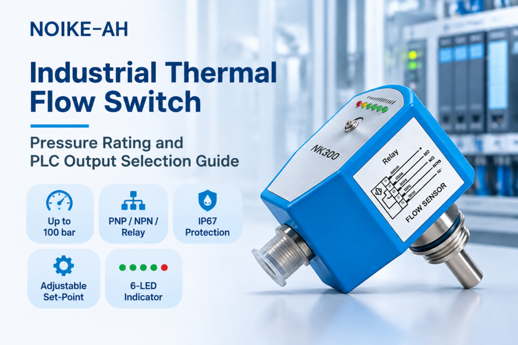
The NOIKE-AH NK300 Electronic Flow Switch offers a published pressure rating of up to 100 bar, PNP / NPN / Relay (SPDT) output options, IP67 protection, built-in electrical protection, and an adjustable switching point.
However, the exact output variant, wiring configuration, process connection, and operating conditions should always be confirmed before installation.
1. Why Pressure Rating Is the First Specification to Check
Thermal dispersion flow switches have no moving mechanical sensing elements. However, the absence of moving parts does not eliminate pressure-related installation risks.
The probe, process connection, sealing components, and installation assembly are all exposed to the pressure inside the pipeline.
If the actual pressure exceeds the allowable rating of any component, leakage or mechanical damage may occur.
Before selecting a flow switch, consider the following parameters:
- Maximum operating pressure: The highest pressure expected during normal operation.
- Pressure surges: Pressure peaks caused by pump starting, stopping, rapid valve closure, or water hammer.
- System design pressure: The maximum pressure specified for the piping or equipment.
- Operating temperature: Check whether the allowable pressure changes with temperature.
- Process connection: Verify the thread type, sealing method, probe construction, and installation configuration.
Is a 100 bar flow switch suitable for a 100 bar pipeline?
Not automatically.
A device rated to 100 bar should not be considered to have additional pressure capacity when installed in a system that can reach 100 bar.
The selection process must account for pressure peaks and the allowable ratings of the complete installed assembly.
If the maximum expected pressure approaches or exceeds the device limit, select a suitably higher-rated instrument or request written confirmation from the manufacturer for the specific configuration.
The NOIKE-AH NK300 has a published maximum pressure rating of 100 bar. This is a product limit, not a recommendation to use it in every application operating near 100 bar.
2. PNP, NPN, or Relay: How to Match the Output to a PLC
One common problem during PLC commissioning is selecting a sensor output that does not match the PLC input circuit.
A sensor may receive power and appear to operate normally, while the PLC input fails to recognize its switching signal.
For conventional three-wire DC switching sensors, the basic output types are:
| Output type | Electrical behavior | Typical compatible PLC input |
|---|---|---|
| PNP (Sourcing) | Supplies positive voltage to the load when active | Sinking input |
| NPN (Sinking) | Switches the signal toward 0 V when active | Sourcing input |
| Relay (SPDT) | Provides a changeover dry contact with COM, NO, and NC terminals | Compatible input circuit using an external signal supply |
PNP Output
A PNP sensor supplies positive voltage to its output when activated.
It is typically used with a sinking PLC input, where the input circuit provides the current path toward 0 V.
PNP sensors are widely used in many modern industrial automation systems.
NPN Output
An NPN sensor switches its output toward 0 V when activated.
It is typically paired with a sourcing PLC input, where the input circuit provides the positive voltage.
NPN sensors are also used in industrial control systems, depending on the PLC input configuration.
Relay SPDT Output
A relay output uses mechanical contacts rather than a transistor switching output.
An SPDT relay normally provides:
- COM: Common contact
- NO: Normally Open contact
- NC: Normally Closed contact
Relay output can be useful when a voltage-free contact is required or when an interface between different control circuits is needed.
However, relay output is not automatically suitable for every voltage or load. Always check the rated switching voltage, current, load category, and contact specifications.
Important: PLC manufacturers may use sourcing and sinking terminology differently. Always identify the input configuration from the PLC input-module wiring diagram and technical documentation.
For further technical guidance, see Schneider Electric’s explanation of PNP and NPN sensor connections.
3. Electrical Ratings: Check More Than PNP or NPN
The output type alone does not confirm electrical compatibility.
Before ordering an industrial thermal flow switch, verify:
- Sensor supply voltage and tolerance
- PLC input voltage range
- Maximum switching current
- Relay contact voltage and current ratings
- Signal polarity
- Connector pin assignment
- Cable wiring configuration
- Whether an additional interface relay is required
The published NK300 specifications include two power-supply options:
- 24 V DC ±20%
- 230 V AC ±15%
The published maximum switching currents are:
- PNP/NPN: 400 mA
- Relay: 4 A
These current values should not be treated as a complete relay voltage or load rating. Confirm the detailed electrical specifications and wiring diagram for the exact ordered variant before connecting an external load.
4. Why IP67 Protection Matters
The installation environment is another important consideration when selecting an industrial thermal flow switch.
The NOIKE-AH NK300 is published with an IP67 protection rating.
IP67 generally indicates protection against dust ingress and temporary immersion under defined test conditions.
However, IP67 does not automatically mean that a device is suitable for continuous immersion, high-pressure washdown, aggressive cleaning chemicals, or every outdoor installation.
Before installation, check:
- Exposure to rain, water spray, or condensation
- Connector sealing and cable-entry protection
- Ambient temperature
- Cleaning chemicals and material compatibility
- Actual installation orientation and environmental conditions
The published NK300 specifications include:
- Medium temperature: -20°C to +80°C
- Ambient temperature: -20°C to +80°C
Always confirm the latest datasheet for the exact product configuration.
5. Switching-Point Adjustment and Flow Indication
A flow switch detects whether the flow condition has crossed a configured threshold.
It is important to distinguish a flow switch from a continuous flow meter.
A flow switch is generally used for:
- Low-flow alarms
- Pump protection
- Cooling-water flow monitoring
- Equipment interlocking
- Flow condition monitoring
It should not be assumed to provide a calibrated numerical flow-rate measurement to the PLC.
For practical commissioning, check whether the device provides:
- Adjustable switching thresholds
- Local flow-status indication
- Defined response time
- Documented initialization time
The NK300 provides a potentiometer for switching-point adjustment and a six-LED flow indicator.
Its published response time is 1–13 seconds, with a typical response of approximately 2 seconds. The initialization time is approximately 8 seconds.
These parameters should be considered when setting PLC alarm delays and designing machine-protection logic.
6. NOIKE-AH NK300 Technical Specifications
The following table summarizes the published specifications of the NOIKE-AH NK300 Electronic Flow Switch.
| Specification | NK300 |
|---|---|
| Measuring principle | Thermal dispersion |
| Applicable media | Water, oil, air |
| Maximum pressure | Up to 100 bar |
| Output options | PNP / NPN / Relay (SPDT NO + NC) |
| Power supply | 24 V DC ±20% or 230 V AC ±15% |
| Maximum switching current | 400 mA (PNP/NPN); 4 A (Relay) |
| Electrical protection | Reverse polarity, overload, short circuit |
| Protection rating | IP67 |
| Switching-point adjustment | Potentiometer |
| Flow indication | 6 LEDs |
| Response time | 1–13 s, typically approximately 2 s |
| Initialization time | Approximately 8 s |
| Medium temperature | -20°C to +80°C |
| Ambient temperature | -20°C to +80°C |
| Probe material | Stainless steel |
| Housing material | PBT |
| Electrical connection | M12 connector / direct cable |
For detailed product information, visit the official NOIKE-AH NK300 Electronic Flow Switch product page.
7. PLC Integration: Pre-Commissioning Checklist
Before putting the flow switch into operation, engineers should complete the following checks:
- Record the normal operating pressure and maximum expected pressure, including transient peaks.
- Confirm that the switch and the complete installation assembly are suitable for the actual pressure and temperature conditions.
- Identify whether the PLC input is sourcing or sinking.
- Select the correct PNP, NPN, or Relay output variant.
- Check the power supply and output electrical ratings.
- Confirm the connector pin assignment and wiring diagram.
- Verify that the IP rating and materials suit the installation environment.
- Install the probe according to the manufacturer’s installation instructions.
- Allow the specified initialization time after power-up.
- Adjust the switching point under representative operating conditions.
- Test normal-flow and low-flow conditions.
- Confirm that the PLC receives the expected switching signal.
- Record the model, output type, set point, and commissioning date.
For safety-related shutdown applications, do not rely on the local LED indicator alone. The complete control-system design, alarm logic, final switching element, and required safety integrity should be evaluated separately.
8. Frequently Asked Questions
Can I change the NK300 output from PNP to NPN after installation?
Do not assume that the output type can be changed in the field.
PNP, NPN, and Relay are listed as different output options within the NK300 product family. Confirm the ordered output variant before purchase.
Can I install a 100 bar NK300 on a pipeline operating at 120 bar?
No.
A pipeline that can reach 120 bar exceeds the published 100 bar pressure limit.
Select an instrument with an adequate pressure rating for the maximum credible pressure, or consult the manufacturer for a suitable alternative.
Can the NK300 relay output directly control a 110 V AC alarm?
Only if the exact relay variant’s contact voltage, current, load category, and wiring requirements permit it.
The published 4 A figure alone does not establish the complete permissible AC switching rating. Check the detailed datasheet before connecting an AC load.
Does the six-LED indicator replace the PLC alarm?
No.
The LED indicator provides local flow-status information for commissioning and maintenance.
The electrical output should be connected to the PLC when automatic control or alarm functions are required.
Does the NK300 display the actual flow rate?
The NK300 is a flow switch designed to detect whether flow has crossed a configured switching threshold.
Its LED indicator provides flow-status information. It should not be treated as a continuous flow meter with a numerical flow-rate output.
Conclusion
Selecting an industrial thermal flow switch for PLC integration requires more than checking the pressure rating or choosing an output type.
Engineers should evaluate pressure conditions, PLC input compatibility, electrical ratings, environmental protection, and switching-point adjustment together.
The NOIKE-AH NK300 provides a published pressure rating of up to 100 bar, PNP/NPN/Relay output options, IP67 protection, an adjustable switching point, and local LED flow indication.
These specifications provide a starting point for evaluating the NK300 in industrial flow-monitoring applications. Always confirm the exact product variant and latest datasheet against the project’s pressure, wiring, and installation requirements.
Author: NOIKE-AH Technical Content Team
Product Reference: NOIKE-AH NK300 Electronic Flow Switch
External Technical Reference: Schneider Electric – PNP and NPN Sensor Connections
Product specifications in this article are based on the published NK300 product information available at the time of writing. Always request and review the latest datasheet, wiring diagram, and order-code details before specifying or installing the device.