
Thermal Flow Switch Principle & Applications
Direct Answer
A thermal dispersion flow switch detects the presence, absence, or specific velocity of liquid or gas flow by measuring how flowing fluid removes heat from a heated sensing element. The sensing probe typically contains a reference temperature sensor, a heated sensor, and an internal heating element. As flow velocity increases, forced convection removes more heat from the heated sensor, changing the temperature difference or the power required to maintain that difference. The electronics process this change and activate the switch output when the measured flow reaches the configured setpoint.
Unlike mechanical flow switches that depend on moving paddles, pistons, or targets, thermal dispersion flow switches have no moving parts. This makes them suitable for applications such as pump dry-run protection, lubrication systems, hydraulic systems, and cooling-water monitoring.
Key Takeaways
- Thermal flow switches use the calorimetric principle, or heat transfer, to detect fluid flow.
- A sensing probe uses temperature measurements to determine how strongly the flowing medium removes heat.
- Because there are no moving mechanical parts, thermal flow switches can reduce mechanical wear and maintenance requirements.
- They can provide high sensitivity for low-flow detection and have negligible pressure drop when properly installed.
- Sensor coating, heavy slurry, and changes in fluid composition can affect thermal measurement performance.
- Thermal flow switches are designed primarily for flow/no-flow detection and control, rather than precision continuous flow measurement.
- The NOIKE NK600 Series is an industrial thermal flow switch designed for demanding liquid-flow monitoring applications.
What Is a Thermal Dispersion Flow Switch?
A thermal dispersion flow switch is a solid-state instrument used to detect the presence, absence, or specific velocity of liquid or gas flow in a pipeline.
Unlike traditional mechanical flow switches that rely on physical movement, thermal dispersion switches operate according to the principles of thermodynamics and heat transfer.
Because they contain no moving parts, thermal flow switches provide a highly reliable and low-maintenance solution for critical flow monitoring applications.
Typical applications include:
- Pump dry-run protection
- Cooling circuit verification
- Lubrication oil monitoring
- Hydraulic system flow monitoring
- Flow/no-flow alarm applications
- Industrial process flow monitoring
The fundamental measurement method is based on how the flowing fluid removes heat from the sensing probe.
How Does a Thermal Flow Switch Work?
The Calorimetric Effect
The core technology behind a thermal flow switch is the calorimetric principle, which is based on heat transfer between the sensing element and the surrounding process medium.
The device uses a sensing probe inserted into the process fluid. The probe contains two precise Resistance Temperature Detectors (RTDs) and an internal heating element.
1. Reference Sensor
The first RTD continuously measures the actual ambient temperature of the flowing fluid.
This provides the reference temperature for the thermal measurement.
2. Heated Sensor
The second RTD is actively heated by the internal electronic circuit.
The system maintains a defined temperature difference, or ΔT, between the heated sensor and the reference sensor.
For example, the heated sensor may be maintained approximately 10°C above the surrounding fluid temperature.
3. Flow Detection
When the process fluid is stationary, the heat generated by the heated sensor remains concentrated around the sensing element.
When fluid begins to move across the probe, the moving fluid absorbs heat and carries it downstream through forced convection.
As flow velocity increases, the cooling effect also increases.
The electronic circuit continuously monitors the resulting thermal change.
Depending on the measurement design, this can be evaluated through:
- The change in temperature difference between the sensors
- The electrical power required to maintain the temperature difference
The electronic system then converts this thermal change into a flow-velocity-related signal.
When the measured velocity reaches the user-defined switching point, the output is activated.
The output may be provided through a relay or transistor output depending on the specific flow switch configuration.
Thermal Flow Switch Working Principle: No Flow vs. Flow
| Operating Condition | Thermal Behavior | Switching Response |
|---|---|---|
| No Flow | Heat remains concentrated around the heated sensor and the temperature difference remains stable. | No-flow condition is detected. |
| Low Flow | Moving fluid begins to remove heat from the heated sensor. | The thermal signal changes according to flow velocity. |
| Higher Flow | Increased fluid movement produces greater cooling through forced convection. | The electronic circuit detects the increased thermal change. |
| Setpoint Reached | The measured thermal condition corresponds to the configured flow velocity. | Relay or transistor output changes state. |
This principle allows a thermal flow switch to detect flow without requiring a mechanical component to physically move.
Key Engineering Advantages of Thermal Dispersion Flow Switches
1. No Moving Parts
Thermal dispersion flow switches do not use mechanical paddles, pistons, or similar moving components.
This eliminates mechanical wear, fatigue, and the possibility of mechanical components becoming seized during operation.
This characteristic is particularly useful in industrial fluid systems where long-term reliability and reduced maintenance are important.
2. Negligible Pressure Drop
The sensing probe is inserted into the process stream without significantly obstructing the pipeline cross-section.
As a result, a thermal flow switch produces negligible pressure drop under normal installation conditions.
This can be advantageous in systems where maintaining available pressure is important.
3. High Sensitivity at Low Flow
Thermal flow switches can detect relatively slow fluid movement.
Unlike mechanical flow switches that require sufficient fluid force to move a paddle or piston, thermal technology detects the heat-transfer effect produced by fluid movement.
This makes thermal dispersion technology suitable for low-flow monitoring applications.
4. Multi-Media Capability
Thermal measurement depends on the heat-transfer characteristics of the process medium.
With appropriate microprocessor-based calibration, a thermal flow switch can be configured for different media.
Examples include:
- Water
- Oil
- Specific process liquids
The calibration can account for differences in thermal properties such as specific heat capacity.
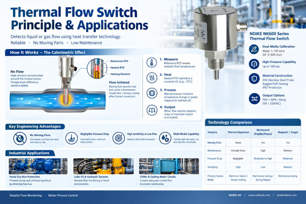
Thermal vs. Mechanical vs. Magnetic Flow Switches
Selecting the appropriate flow switch technology requires consideration of the application, fluid properties, maintenance requirements, and required sensitivity.
| Feature | Thermal Dispersion | Mechanical (Paddle/Piston) | Magnetic / Target |
|---|---|---|---|
| Moving Parts | None | Yes — paddle or piston | Yes — target or spring |
| Maintenance | Virtually none | Higher; susceptible to sticking and wear | Medium |
| Pressure Drop | Negligible | Moderate to high | Moderate |
| Sensitivity | High; suitable for low-flow detection | Lower; requires minimum mechanical force | Medium |
| Primary Failure Mode | Electronic failure or sensor coating | Mechanical seizing or spring fatigue | Mechanical seizing |
The main difference is the measurement mechanism.
Thermal dispersion technology measures the thermal effect of fluid movement, while mechanical technologies rely on physical movement generated by the fluid.
Limitations of Thermal Flow Switches
Thermal dispersion technology provides several engineering advantages, but it is not suitable for every application.
Understanding its limitations is important when selecting a flow switch.
1. Warm-Up Time
A thermal flow switch requires a stabilization period after power-up.
Typically, the device requires approximately 10–15 seconds to heat the sensor and establish the baseline temperature difference.
Therefore, thermal flow switches are not intended for applications requiring sub-millisecond instantaneous flow detection.
For normal industrial flow monitoring, the initial warm-up period should be considered during system design.
2. Sensor Coating and Heavy Slurries
The sensing probe must maintain effective thermal contact with the process medium.
If the process fluid deposits an insulating layer on the sensing probe, such as:
- Thick sludge
- Heavy scale
- Viscous buildup
- Other insulating deposits
the coating can act as a thermal blanket.
This reduces heat transfer between the sensing element and the process fluid and may cause the instrument to incorrectly detect a no-flow condition.
For this reason, thermal flow switches are generally not recommended for heavy slurries or fluids that produce significant insulating deposits on the sensor.
3. Changes in Fluid Composition
Thermal flow measurement depends on the thermal properties of the process medium.
If the composition of the fluid changes significantly, the heat-transfer characteristics can also change.
For example, if a water system is suddenly mixed with a high concentration of glycol or oil that has not been included in the calibration, the change in heat transfer can shift the effective switching point.
Therefore, the process medium and its expected composition should be considered when configuring and calibrating a thermal flow switch.
Industrial Applications of Thermal Flow Switches
Thermal dispersion flow switches are widely used in industrial applications where reliable flow/no-flow detection is required.
Pump Dry-Run Protection
A thermal flow switch can be used to monitor whether sufficient fluid flow is present during pump operation.
If priming is lost and the required flow condition is no longer detected, the flow switch can provide a signal to the control system to shut down the pump.
This helps protect components such as:
- Pump seals
- Bearings
- Pumping elements
from damage associated with operating without adequate fluid flow.
Lube Oil and Hydraulic Systems
Thermal flow switches can be used to monitor oil flow in lubrication and hydraulic systems.
Oil viscosity can vary with temperature, and hydraulic oil systems may also contain microscopic wear particles.
Mechanical flow switches can experience sticking or mechanical seizure under certain operating conditions.
Because thermal flow switches have no moving parts, they can provide a suitable alternative for monitoring oil flow in applications where mechanical movement may be undesirable.
Chiller and Cooling-Water Circuits
Thermal flow switches can monitor coolant flow in:
- Chillers
- Heat exchangers
- Condensers
- Cooling-water circuits
The purpose is to verify that adequate coolant flow is available and help prevent overheating caused by insufficient cooling circulation.
Recommended Instrument: NOIKE NK600 Series Thermal Flow Switch
The NOIKE NK600 Series Thermal Flow Switch is an industrial implementation of thermal dispersion technology designed for demanding liquid-flow monitoring applications.
It is designed for flow/no-flow monitoring and switching rather than precision continuous flow measurement.
NK600 Series Key Specifications
Dual-Media Calibration
The microprocessor provides specific flow ranges for different media:
- Water: 1–150 cm/s
- Oil: 3–300 cm/s
These different ranges address differences in the thermal properties of water and oil.
High-Pressure Capability
The NK600 Series is rated for operating pressures up to:
100 bar
This makes it suitable for high-pressure hydraulic power units (HPUs) and other demanding liquid-flow monitoring applications.
Material Construction
The sensing probe is made from:
304 Stainless Steel
The product also uses a rugged PUR housing and provides:
IP67 protection
This construction is intended for industrial environments where corrosion resistance and enclosure protection are important.
Flexible Output Options
The NK600 Series is available with different output configurations, including:
- PNP
- NPN
- Relay
The relay version can provide:
5 A / 250 VAC
These output options allow the flow switch to interface directly with PLC control systems or to switch motor-control circuits for applications such as pump shutdown.
Engineering Note: Flow Switch vs. Flow Meter
The NK600 Series is designed as a flow switch, not a precision continuous flow meter.
Its primary functions are:
- Flow detection
- No-flow detection
- Flow alarm
- Flow control
- Pump protection
It is not intended for precision continuous flow measurement, custody-transfer applications, or highly dynamic batch-dosing applications.
The NK600 Series is also not recommended for heavy slurries or fluids that leave an insulating coating on the sensing probe.
Selecting a flow switch or flow meter should therefore be based on the actual measurement objective.
If the application only requires confirmation that flow is above or below a defined threshold, a flow switch may be appropriate.
If continuous quantitative flow measurement is required, a suitable flow meter should be considered instead.
How to Select a Thermal Flow Switch
When selecting a thermal flow switch, engineers should evaluate the following parameters:
1. Process Medium
Identify whether the medium is:
- Water
- Oil
- Gas
- Chemical liquid
- Other process fluid
The thermal properties of the medium directly affect heat transfer and therefore switching behavior.
2. Flow Velocity
Determine the expected operating flow velocity and the required switching point.
The selected instrument should provide an appropriate measurement and switching range.
3. Operating Pressure
Check the maximum process pressure before selecting the sensor construction.
For the NK600 Series, the rated operating pressure is up to 100 bar.
4. Sensor Material
Check compatibility between the sensing probe material and the process medium.
The NK600 Series uses a 304 stainless steel sensing probe.
5. Fluid Cleanliness
Determine whether the medium contains:
- Sludge
- Scale-forming materials
- Suspended solids
- High-viscosity deposits
Heavy coating on the sensing probe can affect heat transfer and switching accuracy.
6. Output Type
Select the required output according to the control system.
Common options include:
- PNP
- NPN
- Relay
7. Required Function
Confirm whether the application requires:
- Flow/no-flow detection
- Low-flow alarm
- Pump protection
- Cooling-water verification
- Continuous flow measurement
A thermal flow switch is primarily intended for switching and monitoring rather than precision continuous flow measurement.
Frequently Asked Questions
Does a thermal flow switch cause a pressure drop in the pipeline?
A thermal flow switch generally causes negligible pressure drop because the sensing probe does not significantly obstruct the pipeline cross-section and does not use a moving paddle or piston.
How long does a thermal flow switch take to respond to a flow change?
The response to a sudden flow change is typically around 1–2 seconds.
However, the device requires an initial warm-up period of approximately 15 seconds after power-on to stabilize the internal heating element and establish the operating thermal condition.
The initial warm-up time should therefore be distinguished from the response time to a flow change during normal operation.
Can a thermal flow switch be used for dirty water or heavy slurries?
Thermal flow switches are generally not recommended for heavy slurries or fluids that coat the sensing probe.
Dirt, scale, sludge, or other insulating deposits can reduce heat transfer between the probe and the process fluid.
This may result in false no-flow alarms.
Clean or mildly dirty liquids are generally more suitable.
Why use a thermal flow switch for oil instead of a mechanical flow switch?
Oil viscosity can vary significantly with temperature, while hydraulic oil systems may also contain microscopic wear particles.
Under certain conditions, mechanical paddle-type flow switches can become stuck or seize.
A thermal flow switch has no moving parts, so it eliminates mechanical sticking and seizure associated with moving components.
This makes thermal technology suitable for many oil and lubrication flow-monitoring applications.
Can a thermal flow switch measure continuous flow rate?
A thermal flow switch is primarily designed for flow/no-flow detection and switching.
It should not automatically be considered a precision continuous flow meter.
For applications involving custody transfer, precise continuous measurement, or highly dynamic batch dosing, a dedicated flow meter designed for the required measurement accuracy should be selected.
Conclusion
A thermal dispersion flow switch detects fluid flow by measuring the heat-transfer effect produced when moving liquid or gas removes heat from a heated sensing element.
Its main advantages are no moving parts, negligible pressure drop, high sensitivity to low flow, and low maintenance requirements.
However, engineers should also consider warm-up time, sensor coating, heavy slurries, and changes in fluid composition when selecting and installing a thermal flow switch.
For industrial applications such as pump dry-run protection, hydraulic and lubrication systems, and chiller or cooling-water monitoring, thermal dispersion technology provides a practical method for reliable flow/no-flow detection.
The NOIKE NK600 Series Thermal Flow Switch provides water and oil flow ranges, operation up to 100 bar, a 304 stainless steel sensing probe, IP67 protection, and PNP, NPN, or relay output options for industrial flow monitoring and control.
Request a Thermal Flow Switch for Your Application
Selecting the correct flow switch depends on the process medium, flow velocity, operating pressure, temperature, installation conditions, and required output.
For technical specifications, application evaluation, or OEM/ODM requirements, contact NOIKE-AH with your process parameters.
NOIKE-AH — Professional Flow Instrument Manufacturer
Internal References & Resources:
1.Core Concepts:
Thermal Flow Switch Principle & Applications
2.Technology Comparison:
Why Mechanical Flow Switch Failure in Oil Systems? Mechanical vs. Thermal Flow Switch
3.Selection Guide
How to Select a Flow Switch for Water, Oil, and Hydraulic Systems
4.Product Specifications:



