
Direct Answer
PLC analog input impedance mismatch usually means the 4–20mA current loop load is not suitable. If the PLC input resistance is too high, or if display meters, isolators, external resistors or long cables are added in series, the pressure transmitter may not have enough voltage to drive the loop current up to 20mA. The result can be low readings, unstable values, full-scale failure or no signal.
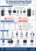
A 4–20mA current loop includes a power supply, transmitter, receiver/controller and wiring. The loop power supply must provide enough voltage to drive all loop loads. Fluke explains that 4–20mA loops are commonly powered by 24VDC and use current variation to represent variables such as pressure, temperature and flow.
What Is PLC Analog Input Impedance?
In a 4–20mA input channel, PLC input impedance is the load resistance seen by the current loop. Many analog input modules use an internal resistor to convert current into voltage for A/D conversion.
For example:
| Input Resistance | Voltage at 4mA | Voltage at 20mA |
|---|---|---|
| 125Ω | 0.5V | 2.5V |
| 250Ω | 1V | 5V |
| 500Ω | 2V | 10V |
AutomationDirect documentation shows some current input modules with 125Ω per channel and others with 250Ω per channel. Rockwell Automation’s Allen-Bradley Micro800 2080-IF4 analog input module also lists 250Ω input impedance in current mode.
Common Problems
| Problem | Likely Cause |
|---|---|
| Signal cannot reach 20mA | Loop load too high or supply voltage too low |
| PLC reading is lower than actual pressure | Input impedance, scaling or loop voltage issue |
| Reading jumps | Grounding, interference or wrong input mode |
| Signal becomes abnormal after adding display/isolator | Added load causes voltage drop |
| Transmitter works alone but fails with PLC | PLC input configuration or load mismatch |
| PLC and VFD readings differ | Different scaling, input mode or load path |
Fluke notes that newly added loop loads or weak power supplies can prevent the loop from maintaining full current at 20mA, causing the output to level off below 20mA.
How to Diagnose
- Check the PLC module manual
Confirm whether the channel is current input or voltage input, and check the input impedance. - Check whether an external resistor is needed
If the PLC module is voltage input only, a 250Ω resistor may be used to convert 4–20mA to 1–5V. If the PLC already has current input, adding another resistor may overload the loop. - Calculate loop load
Include PLC input resistance, cable resistance, isolator load, display load and any added resistor. - Check supply voltage margin
The power supply must cover the transmitter operating voltage plus the voltage drop across all loop loads at 20mA. - Measure loop current
Use a loop calibrator, process clamp meter or multimeter to confirm whether the current changes from 4mA to 20mA. Fluke describes using a process clamp meter to verify mA loop current without breaking the loop. - Isolate transmitter and PLC input
AutomationDirect recommends isolating the transmitter from the PLC input to confirm whether the transmitter is sending the correct signal before blaming the PLC input.
NOIKE-AH Application Solution
NOIKE-AH pressure transmitters can provide continuous pressure feedback to PLC, VFD and control panel systems. NOIKE-AH’s product range includes Pressure Series products such as pressure gauges, pressure switches, pressure sensors and pressure transmitters. (Noike-AH)
Recommended configuration:
- use a pressure transmitter for continuous pressure feedback;
- confirm PLC current input mode and input impedance;
- use a signal splitter or isolator when PLC and VFD both need the same signal;
- use an intelligent pressure switch for independent alarm and protection;
- use a digital pressure gauge for local pressure verification.
Conclusion
PLC analog input impedance mismatch can cause low 4–20mA signal, unstable readings, full-scale failure or no signal. The correct troubleshooting process is to check the PLC input type, input impedance, external resistor, transmitter load capability, 24VDC power margin, loop load, grounding and scaling.
NOIKE-AH recommends using pressure transmitters for continuous feedback, intelligent pressure switches for protection and digital pressure gauges for field verification. In pump control panels and constant pressure systems, checking input impedance and loop load before commissioning helps reduce signal problems and after-sales misjudgment.



