
Direct Answer
When a pressure transmitter has no 4–20mA signal, the most common causes are not always sensor failure. They are often insufficient 24VDC power, reversed polarity, broken loop wiring, PLC analog input not included in the loop, or wrong PLC input configuration.
A 4–20mA current loop usually includes a power supply, transmitter, receiver/controller and wiring connected in series. 24VDC is commonly used in industrial systems. The 4mA live zero helps distinguish a valid zero reading from faults such as broken wires or power loss.
Why Insufficient 24VDC Causes No Signal
The transmitter needs enough voltage to drive the entire current loop, including the transmitter, PLC input resistance, cable resistance and any isolator or display in series. If loop voltage is not enough, the transmitter may not maintain the correct current, causing low readings, no signal or unstable output.
Common signs:
| Symptom | Possible Cause |
|---|---|
| PLC reads zero | No 24VDC, fuse open, loose terminal |
| Signal cannot reach 20mA | Insufficient loop voltage or excessive load |
| Intermittent signal | Weak power supply or voltage drop |
| Signal fails after adding more devices | Loop load too high |
| Long cable causes low reading | Cable voltage drop |
What Happens If Polarity Is Reversed?
A 2-wire pressure transmitter has polarity. A typical loop is:
24VDC+ → Transmitter+ → Transmitter- → PLC AI+ → PLC AI-/COM → 24VDC-
If transmitter polarity or PLC AI polarity is reversed, the loop may produce 0mA, abnormal values or no signal. Some transmitters have reverse polarity protection, but they still will not output correctly if wired incorrectly.

Why an Open Loop Gives 0mA
A 4–20mA current loop must be complete. If any point is disconnected, current cannot flow and the PLC may read 0mA. Because 4mA is the valid live zero, a 0mA reading usually indicates a fault such as broken wire, power loss or open loop.
Common open-loop points:
- loose 24VDC+ terminal;
- broken transmitter wire;
- loose PLC AI+ terminal;
- AI-/COM not connected to 0V;
- wet or oxidized connector;
- wrong terminal block connection.
Troubleshooting Steps
- Check the transmitter nameplate
Confirm power supply, output signal and wiring type. - Measure 24VDC power
Check voltage at the power supply and transmitter terminals. - Check polarity
Confirm V+, V-, OUT, AI+, AI- and COM. - Confirm loop continuity
For 2-wire transmitters, PLC AI must be in series with the loop. - Measure loop current
A proper signal should be between 4mA and 20mA. Fluke notes that 4–20mA loop verification includes testing transmitter output, wiring, control system input and return wiring. - Isolate transmitter and PLC input
AutomationDirect recommends separating the transmitter from the PLC input to verify whether the transmitter is sending the correct signal; a 250Ω resistor can convert loop current into 1–5VDC for checking. - Check PLC configuration and scaling
Make sure the analog input is configured for 4–20mA current input and the engineering range matches the transmitter range.
NOIKE-AH Application Solution
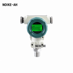
NOIKE-AH pressure transmitters can provide standard pressure feedback signals for PLC, VFD and control panel applications. NOIKE-AH’s Pressure Series includes pressure gauges, pressure switches, pressure sensors and pressure transmitters, and its pressure sensors and transmitters support outputs such as 4–20mA / HART / Modbus. (Noike-AH)
Recommended configuration:
- use a pressure transmitter for continuous pressure feedback;
- use an intelligent pressure switch for independent alarm and protection;
- use a digital pressure gauge for local pressure verification;
- use shielded cable, proper grounding and signal isolation when VFD interference is present.
Conclusion
If a pressure transmitter has no signal, check power, polarity and loop continuity before replacing the transmitter. The correct diagnostic order is:
- verify 24VDC supply;
- check V+, V-, OUT, AI+, AI- and COM wiring;
- confirm that the 2-wire loop is closed;
- measure 4–20mA loop current;
- check PLC current input mode and scaling;
- inspect loose terminals, broken wires, wet connectors and interference.
NOIKE-AH recommends using pressure transmitters for continuous feedback, intelligent pressure switches for protection and digital pressure gauges for field verification. This helps reduce wiring mistakes, no-signal faults and pump control panel commissioning time.



