
How Air Bubbles Affect Flow Meter Accuracy
Direct Answer
Air bubbles can significantly affect flow meter accuracy when measuring liquids, but the extent of the error depends on the measurement principle, bubble concentration, bubble size, flow conditions, and installation configuration. Entrained air can cause unstable readings, measurement deviations, signal loss, or incorrect totalized volume. The impact is particularly important for ultrasonic, vortex, Coriolis, and some other flow meter technologies.
In industrial piping systems, air may enter through pump suction lines, leaking connections, insufficient filling, dissolved gas released from the liquid, or changes in pressure and temperature. Identifying the source of the air and selecting a flow meter suitable for the actual process conditions are essential steps toward reliable measurement.
Key Takeaways
- Air bubbles can distort measurement signals. Their effects vary with the flow meter’s operating principle and the characteristics of the gas-liquid mixture.
- Different flow meters respond differently. Ultrasonic meters may experience signal attenuation, vortex meters may produce disturbed vortex signals, and Coriolis meters can experience errors in mass flow and density measurement.
- Electromagnetic flow meters are not automatically immune to air. Gas pockets and intermittent liquid contact can cause unstable or inaccurate readings.
- Installation conditions matter. Proper pipe filling, suitable meter orientation, adequate backpressure, and effective air removal can reduce measurement problems.
- Troubleshooting should begin with the process. Check for air ingress, pump cavitation, partially filled pipes, and gas accumulation before assuming that the meter itself is defective.
1. What Are Air Bubbles in a Liquid Flow System?
Air bubbles in a liquid pipeline are small gas pockets carried by the flowing liquid. Depending on their origin and behavior, they may appear as isolated bubbles, dispersed microbubbles, larger gas pockets, or intermittent gas slugs.
In industrial applications, the term entrained gas is often used to describe gas dispersed or carried within a liquid stream. The gas may be air, another process gas, or a mixture of gases, depending on the application.
Air bubbles are common in many systems, including:
- Industrial water supply and circulation systems
- Wastewater treatment and pumping stations
- Chemical dosing and liquid transfer systems
- Hydraulic and lubrication circuits
- Food and beverage processing lines
- Cooling water and heat-exchange systems
- Liquid filling and batching equipment
The presence of gas does not always indicate a fault. Some processes intentionally mix gas and liquid. However, when a flow meter is selected and calibrated for single-phase liquid measurement, unexpected gas entrainment can compromise the reliability of its readings.
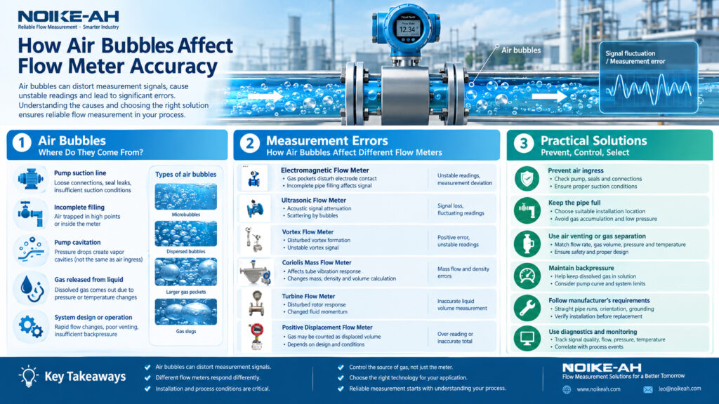
Common Sources of Air in Liquid Pipelines
1. Air entering through the pump suction line
Loose connections, damaged seals, or inadequate suction conditions may allow air to enter a pump system. This is particularly relevant to systems operating under negative gauge pressure at the suction side.
2. Incomplete pipeline filling
During commissioning, maintenance, or startup, air may remain trapped at high points in the pipeline or inside the flow meter.
3. Pump cavitation
When local liquid pressure falls sufficiently, vapor cavities can form and subsequently collapse as pressure increases. Cavitation is not the same as air entering the system, although both phenomena can produce noise, vibration, and unstable process conditions.
4. Gas released from the liquid
Dissolved gas can come out of solution when pressure decreases or temperature changes. The resulting bubbles may appear even when there is no external air leak.
5. Improper system design or operation
Rapid changes in flow, poor venting arrangements, insufficient backpressure, or unsuitable piping configurations may contribute to gas accumulation or intermittent gas entrainment.
Understanding the source is important because removing existing bubbles without addressing the underlying cause may only provide temporary improvement.
2. How Do Air Bubbles Affect Flow Meter Accuracy?
Air bubbles can influence a flow meter through several mechanisms. The dominant mechanism depends on how the instrument detects flow.
2.1 Disturbance of the Measurement Signal
Ultrasonic flow meters rely on acoustic signals traveling through the process medium. Gas bubbles create strong differences in acoustic impedance between the gas and liquid phases. These differences can scatter, reflect, or attenuate ultrasonic signals.
When the signal becomes too weak or unreliable, the meter may show fluctuating readings, produce a signal-quality alarm, or temporarily lose measurement.
2.2 Changes in the Effective Flowing Medium
A liquid containing gas is a two-phase mixture rather than a homogeneous liquid. Its effective density, compressibility, and flow behavior differ from those of the liquid alone.
This is particularly important for Coriolis mass flow meters, which infer flow and density from the dynamic response of vibrating measuring tubes. Entrained gas can disturb that response and cause errors in mass flow, density, and calculated volume flow.
The magnitude and direction of the error depend on factors such as bubble size, gas fraction, liquid viscosity, meter geometry, and operating conditions. It is therefore not technically correct to assume that all Coriolis meters will always over-read or under-read when air is present.
2.3 Disturbance of Vortex Formation
Vortex flow meters measure flow using the periodic vortices generated downstream of a bluff body. Entrained gas in a liquid can interfere with vortex formation and detection.
This may result in positive measurement error, unstable readings, or unreliable operation. Vortex meters are generally intended for suitable single-phase flow conditions unless the manufacturer explicitly supports the intended multiphase application.
2.4 Intermittent Wetting and Gas Pockets
Some flow meters require a continuously filled pipe and stable contact between the liquid and the sensing elements. Large gas pockets or a partially filled pipe can interrupt that condition.
For example, gas accumulating around the electrodes of an electromagnetic flow meter may reduce effective liquid contact and destabilize the measured signal. A pipe that is not completely full can create additional problems because the meter’s measurement assumptions may no longer be satisfied.
2.5 Incorrect Interpretation of Mixture Flow
A flow meter’s displayed value must be interpreted according to the quantity it measures.
A volumetric meter, for example, may respond to the combined gas-liquid stream within its sensing region, while a Coriolis meter measures the mass of the mixture passing through its measuring tubes. Neither behavior necessarily provides the desired liquid-only flow rate.
If the process requires the actual liquid flow rate, simply reading the indicated mixture flow may not provide an accurate result.
3. How Air Bubbles Affect Different Types of Flow Meters
Not all flow meters respond to entrained air in the same way. The following comparison is intended for applications in which a meter is being considered for liquid service.
| Flow meter type | Typical effect of air bubbles | Practical consideration |
|---|---|---|
| Electromagnetic flow meter | Unstable readings or measurement deviation when gas pockets disturb electrode contact or the flow profile | Maintain a full, properly grounded pipe and minimize gas accumulation |
| Ultrasonic flow meter | Signal attenuation, scattering, poor signal quality, or loss of measurement | Check the meter technology, acoustic path, and allowable gas content |
| Vortex flow meter | Disturbed vortex formation and potentially positive or unstable readings | Prefer suitable single-phase liquid service |
| Coriolis mass flow meter | Errors in mass flow, density, and calculated volume flow | Confirm the manufacturer’s allowable entrained-gas conditions and diagnostic capabilities |
| Turbine flow meter | Disturbed rotor response and potentially inaccurate liquid-volume measurement | Verify that the application remains within the meter’s specified operating conditions |
| Positive displacement flow meter | Gas may be counted as displaced volume, depending on the design and operating conditions | Prevent gas entrainment when accurate liquid-only measurement is required |
These effects are typical engineering considerations, not guaranteed error directions for every model. Actual performance must be verified against the instrument manufacturer’s specifications and the application conditions.
3.1 Electromagnetic Flow Meters
Electromagnetic flow meters operate according to Faraday’s law of electromagnetic induction. A conductive liquid moving through a magnetic field generates a voltage that is related to its average velocity.
They are widely used for conductive liquids in water treatment, chemical processing, and industrial circulation systems. However, the presence of air can still affect measurement stability.
Potential symptoms include:
- A fluctuating instantaneous flow value
- Unexpected changes in the totalized volume
- Intermittent low-flow readings
- Unstable measurement when the pump starts or stops
Air bubbles do not automatically make an electromagnetic flow meter unsuitable. The important factors include the amount and distribution of gas, whether the pipe remains full, the meter’s design, and the process requirements.
For liquid applications with recurring air entrainment, investigate the source of the gas and verify the manufacturer‘s recommendations before changing the meter.
3.2 Ultrasonic Flow Meters
Ultrasonic flow meters use sound waves to determine fluid velocity. Depending on the design, they may measure the difference in transit time between acoustic signals traveling with and against the flow, or use another ultrasonic measurement method.
Gas bubbles can interfere with acoustic transmission because gas and liquid have very different acoustic properties.
Typical symptoms include:
- Fluctuating flow readings
- Reduced signal strength
- Unstable measurement at higher gas concentrations
- Signal-quality warnings or measurement interruption
Clamp-on transit-time ultrasonic meters can be particularly sensitive to conditions that prevent reliable acoustic transmission through the pipe wall and liquid. However, sensitivity varies with the meter design, signal processing, installation, and bubble concentration.
If gas entrainment is expected, confirm the manufacturer’s permitted operating conditions. Do not assume that all ultrasonic flow meters can measure a gas-liquid mixture reliably.
3.3 Vortex Flow Meters
Vortex flow meters determine flow by detecting vortices generated behind a bluff body. Their performance depends on the stability and detectability of the vortex-shedding process.
When gas bubbles are present in a liquid stream, they can disturb the vortex pattern and the sensor signal. This can cause a positive error, unstable readings, or unreliable measurement.
In applications involving process water, cooling water, or other liquids, investigate whether air is entering the system before concluding that the vortex sensor or electronics have failed.
For significant or persistent gas entrainment, consider a measurement technology specifically suitable for the process rather than relying on a vortex meter designed for single-phase service.
3.4 Coriolis Mass Flow Meters
Coriolis flow meters determine mass flow from the response of vibrating measuring tubes. They can also provide density measurements and, depending on the instrument, calculated volume flow.
Entrained gas can disturb the tube’s dynamic response. The result may include deviations in mass flow and density, as well as a greater error in the calculated volume flow.
The behavior is complex. Free bubbles and finely dispersed bubbles can produce different effects, and the response depends on the fluid properties and meter design.
Some Coriolis meters offer diagnostics or application-specific functions to improve performance in gas-entrained liquids. Such capabilities must be verified for the exact model and operating conditions; they should not be interpreted as a guarantee of accurate measurement at any gas concentration.
3.5 Turbine and Positive Displacement Flow Meters
Turbine flow meters infer flow from rotor rotation. Gas entrainment changes the fluid’s effective density and momentum transfer, potentially changing the rotor response and indicated liquid flow.
Positive displacement flow meters measure fluid by trapping and transferring defined volumes through a measuring chamber. If gas passes through the meter, it may contribute to the displaced volume even though it does not represent the same quantity of liquid.
For applications involving liquid dosing, chemical consumption, or commercial transfer, gas entrainment can therefore create significant discrepancies between the indicated quantity and the actual liquid delivered.
The appropriate corrective action depends on the meter design, the gas fraction, and whether the required measurement is total mixture flow or liquid-only flow.
4. Real-World Industrial Conditions That Can Cause Inaccurate Readings
The following examples illustrate how air-related measurement problems may appear during routine operation.
Case 1: Water Circulation System With Unstable Flow Readings
Observed problem: An electromagnetic flow meter displays fluctuating readings after a circulation pump starts.
Possible causes:
- Air remaining in the pipeline after maintenance
- Air entering through a suction-side connection
- Gas accumulating at a high point
- The pipe not remaining completely full during startup
Recommended checks:
- Confirm that the pipeline is fully filled under normal operating conditions.
- Inspect the pump suction line and relevant connections for possible air ingress.
- Check whether the fluctuation coincides with startup, venting, or changes in pump operation.
- Verify the meter installation, grounding, and diagnostic status.
- Compare the indicated flow with an independent measurement where practical.
The objective is to distinguish an actual process fluctuation from a measurement problem before adjusting the meter.
Case 2: Clamp-On Ultrasonic Meter on a Liquid Pipeline
Observed problem: A clamp-on ultrasonic meter intermittently loses its flow reading.
Possible causes:
- Gas bubbles attenuating the ultrasonic signal
- Inadequate acoustic coupling between the transducers and the pipe
- Incorrect transducer spacing or mounting
- Pipe conditions or fluid properties outside the meter’s specified limits
Recommended checks:
Inspect transducer mounting and coupling first, then review the instrument’s signal-quality indicators. If signal quality deteriorates when the pump draws air or the process changes, investigate the gas source.
A signal-loss problem should not automatically be attributed to air bubbles because installation and pipe-wall conditions can produce similar symptoms.
Case 3: Liquid Dosing System With Incorrect Batch Totals
Observed problem: The totalized quantity from a dosing meter does not match the expected liquid consumption.
Possible causes:
- Air entering through an empty or poorly primed suction line
- Gas released from the liquid during pressure changes
- Incomplete filling of the measuring chamber
- A difference between mixture volume and actual liquid volume
Recommended checks:
Verify that the suction line remains properly primed, inspect the system for air ingress, and check the meter’s suitability for the liquid and operating conditions.
Where the process requires precise liquid dosing, consider whether a suitable gas separator or a different measurement arrangement is necessary. Its effectiveness must be confirmed for the expected flow rate, liquid properties, and gas load.
These examples are diagnostic scenarios rather than universal failure patterns. The correct conclusion should be based on measured process conditions and instrument data.
5. How to Reduce the Effect of Air Bubbles on Flow Measurement
Preventing air from entering the measuring section is often more reliable than trying to compensate for an unknown gas concentration after it has entered the pipeline.
5.1 Prevent Air From Entering the Pipeline
Inspect pump suction connections, seals, valves, and other potential air-entry points. In systems operating under suction, a connection can admit air even when liquid is not visibly leaking outward.
Check the pump’s operating conditions against its design requirements, including suction pressure and available net positive suction head where applicable.
If cavitation is suspected, evaluate the hydraulic conditions rather than treating it as a simple air-leak problem.
5.2 Keep the Measuring Pipe Completely Filled
Many inline liquid flow meters require a full pipe for reliable measurement.
Where the process configuration permits, select an installation location that maintains a full pipe under normal operating conditions. Avoid locations where gas is likely to collect or where low pressure can cause dissolved gas to come out of solution.
For horizontal installations, consider the behavior of gas and liquid in the pipe and the specific orientation requirements of the meter. A universal rule such as always installing the meter horizontally or vertically is not appropriate for every technology.
5.3 Use Appropriate Air Venting and Gas Separation
Where gas accumulation is a recurring problem, an air vent or gas separator may be appropriate.
The design should account for:
- Minimum and maximum liquid flow rates
- Expected gas volume and bubble size
- Operating pressure and temperature
- Liquid viscosity and process compatibility
- Available installation space
- Pressure loss and maintenance requirements
A simple vent is not suitable for every closed or pressurized process. The venting arrangement must be designed to maintain safe process containment and prevent unintended liquid release.
5.4 Maintain Suitable Backpressure
In some systems, sufficient downstream pressure helps prevent dissolved gas from coming out of solution. However, the required pressure depends on the liquid, temperature, gas solubility, and system configuration.
Backpressure should be evaluated against the pump curve, piping pressure rating, and process design limits. Increasing pressure without understanding the cause of gas formation is not a universal solution.
5.5 Follow the Manufacturer’s Installation Requirements
The meter should be installed according to the specific manufacturer’s instructions, including any requirements for straight pipe runs, orientation, grounding, transducer placement, and full-pipe operation.
Incorrect installation can create measurement errors that resemble the effects of air bubbles. Confirming the installation before replacing the instrument helps avoid unnecessary maintenance costs.
5.6 Use Suitable Diagnostics and Process Monitoring
When available, record signal quality, density, flow rate, alarms, and other relevant process variables.
Correlating measurement instability with pump startup, valve movement, pressure changes, or process temperature can help identify the cause more quickly.
A consistent diagnostic procedure is generally more effective than repeatedly changing calibration factors to compensate for fluctuating readings.
6. How to Select a Flow Meter for Applications With Air Bubbles
When air entrainment cannot be completely eliminated, flow meter selection should begin with the process requirements rather than the meter’s nominal accuracy specification alone.
Step 1: Define the Measurement Objective
Determine whether the application requires:
- Actual liquid volumetric flow
- Total gas-liquid mixture volume
- Mass flow of the mixture
- Density measurement
- Batch or dosing accuracy
These quantities are not interchangeable. A meter that measures the mixture correctly may still be unsuitable if the required output is liquid-only flow.
Step 2: Characterize the Gas-Liquid Conditions
Establish, as far as practical:
- Expected gas volume fraction
- Whether bubbles are continuous or intermittent
- Approximate bubble size and distribution
- Minimum and maximum flow rates
- Operating pressure and temperature
- Liquid conductivity, viscosity, and composition
These details help determine which measurement technologies are suitable.
Step 3: Compare Technologies Against the Actual Application
| Application condition | Engineering consideration |
|---|---|
| Conductive liquid with occasional small bubbles | An electromagnetic meter may be suitable if the pipe remains full and gas-related errors are acceptable |
| Liquid measured by clamp-on transit-time ultrasound | Confirm that gas content remains within the manufacturer’s limits for reliable acoustic measurement |
| Liquid with substantial or recurring gas entrainment | Evaluate gas separation or a meter specifically designed and validated for the two-phase service |
| Accurate liquid dosing | Minimize gas entering the meter and verify the complete dosing arrangement |
| Mass flow and density measurement | Review the Coriolis meter’s gas-handling specifications and diagnostics |
| Flow measurement in a system with frequent pump startup and shutdown | Evaluate priming, air ingress, full-pipe conditions, and transient operating behavior |
No technology should be selected solely because it is described as suitable for liquids or because it has a high published accuracy under specified test conditions. The actual gas-liquid conditions must be included in the selection process.
Step 4: Verify Performance Under Operating Conditions
Before finalizing the selection, confirm the manufacturer’s specifications for the expected fluid, pressure, temperature, flow range, and gas content.
Where measurement uncertainty is critical, consider a practical validation test using representative process conditions. If a gas separator or specialized gas-handling function is proposed, evaluate its performance under the expected operating range.
7. Common Mistakes When Troubleshooting Air-Related Flow Errors
Mistake 1: Assuming every unstable reading is caused by air.
Electrical interference, poor grounding, changing process flow, incorrect installation, sensor contamination, and low-flow operation can produce similar symptoms.
Mistake 2: Treating cavitation and air entrainment as the same problem.
Cavitation involves vapor cavities formed by local pressure reduction. Air entrainment involves gas carried into or released within the liquid. They can occur together but require different diagnostic checks.
Mistake 3: Assuming electromagnetic flow meters are unaffected by bubbles.
Electromagnetic meters have important advantages for conductive liquids, but gas pockets, incomplete pipe filling, and intermittent electrode contact can still compromise readings.
Mistake 4: Applying a fixed correction factor to fluctuating measurements.
A fixed calibration adjustment cannot reliably compensate for a gas concentration that changes with time or operating conditions.
Mistake 5: Replacing the meter before checking the process.
If the actual cause is air entering through a pump suction line or gas collecting at a high point, a replacement meter may exhibit the same symptoms.
A structured troubleshooting procedure should verify the process conditions, installation, and measurement signals before the instrument is declared defective.
8. Frequently Asked Questions (FAQ)
Q1: Can air bubbles cause a flow meter to read higher than the actual flow?
Yes, under some conditions. For example, entrained gas can cause positive measurement errors in certain vortex flow meter applications. Other meter technologies may under-read, over-read, fluctuate, or lose the signal. The error direction depends on the measurement principle and process conditions.
Q2: Are electromagnetic flow meters affected by air bubbles?
Yes. Electromagnetic flow meters can experience unstable or inaccurate readings when gas pockets interfere with electrode contact, when the pipe is not completely full, or when the gas-liquid flow disrupts the measurement conditions. The magnitude of the effect depends on the meter design and application.
Q3: Why does my ultrasonic flow meter lose its signal when the pump starts?
Air entering the pipeline during startup may attenuate or scatter ultrasonic signals. However, poor transducer coupling, incorrect mounting, unsuitable pipe conditions, and other installation issues can cause similar symptoms. Check signal-quality indicators and correlate them with the pump’s operating conditions.
Q4: Can an air separator improve flow meter accuracy?
It can help when entrained gas is the main cause of the measurement error and the separator is properly sized for the process. Performance depends on gas concentration, bubble size, liquid properties, pressure, and flow rate. An air separator cannot correct unrelated electrical, installation, or calibration problems.
Q5: Does increasing pipeline pressure eliminate air bubbles?
Not necessarily. Increasing pressure can help keep some dissolved gases in solution, depending on the fluid and operating conditions. However, existing free-gas pockets may remain, and air entering through a suction leak will not be corrected simply by changing downstream pressure. Any pressure adjustment must remain within the system’s design limits.
Q6: Which flow meter is best for liquids containing air bubbles?
There is no universally best flow meter for every gas-liquid application. The appropriate choice depends on the required measurement, gas fraction, bubble characteristics, liquid properties, operating range, and acceptable uncertainty. For accurate liquid-only measurement, controlling or separating the gas is often an important part of the solution.
Q7: How can I determine whether air bubbles are causing my flow meter’s inaccurate readings?
Check whether the reading changes with pump startup, suction pressure, valve position, or system venting. Review the meter’s diagnostics and verify that the pipe is full. If necessary, compare the reading with an independent measurement method suitable for the process. Confirm the diagnosis before changing the calibration or replacing the meter.
9. Conclusion
Air bubbles are a common but often overlooked source of flow measurement problems in industrial liquid systems. Depending on the measurement technology, entrained gas may distort acoustic signals, disturb vortex formation, affect electromagnetic electrode contact, or change the dynamic response of a Coriolis meter.
The most effective approach combines three steps: identify the source of the gas, verify the installation and operating conditions, and select a flow meter suited to the actual process. Where gas entrainment is unavoidable, the meter’s ability to handle the expected two-phase conditions must be confirmed rather than assumed.
Reliable flow measurement begins with understanding the fluid and the system, not simply replacing the instrument.
10. Need Help Selecting a Flow Meter for Your Application?
Choosing a suitable flow meter requires more than knowing the pipe diameter and nominal flow range. Gas entrainment, fluid properties, operating pressure, temperature, and installation conditions can all affect measurement performance.
NOIKE-AH provides industrial flow measurement solutions for a range of process applications. If you are experiencing unstable readings or selecting a flow meter for a liquid system that may contain air bubbles, share your application details with our team for a technical discussion.
Contact NOIKE-AH
For a more accurate recommendation, include the fluid type, pipe size, flow range, operating pressure and temperature, flow meter model, and the conditions under which the reading becomes unstable.



