
PID
In a constant pressure water supply system, the VFD adjusts pump speed according to the pressure feedback signal from a pressure transmitter.
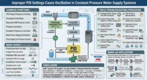
If the PID parameters are not properly tuned, the system may show pressure oscillation, VFD frequency hunting, unstable pump speed, and repeated pressure overshoot.
A typical control chain is:
pressure transmitter → 4–20mA feedback → PLC/VFD analog input → scaling → filtering → PID control → VFD output frequency → pump speed → pipe pressure
ABB’s pump control documentation also describes pressure sensor feedback, analog input, PID mode, and multi-pump drive control as part of the same control structure.
Common Symptoms
Typical field symptoms include:
- VFD output frequency repeatedly rising and falling;
- pump noise changing periodically;
- HMI pressure trend moving like a wave;
- pressure overshoot after pump acceleration;
- unstable pressure at low flow;
- multi-pump systems oscillating during pump staging;
- false high-pressure or low-pressure alarms.
Main Causes
The problem is usually caused by one or more of the following:
| Cause | Effect |
|---|---|
| Proportional gain too high | VFD reacts too strongly to small pressure errors |
| Integral time too short | accumulated correction causes overshoot |
| Feedback filter too small | PID follows signal noise |
| Feedback filter too large | control response becomes delayed |
| Accel/decel time too short | pump speed changes too aggressively |
| Deadband too small | system keeps correcting around setpoint |
| Pressure signal noise | VFD follows unstable feedback |
| Low-flow condition | pump operates in an unstable region |
| Pressure tank failure | system loses hydraulic buffering |
ABB’s PID documentation explains that proportional, integral, and derivative actions affect current error, accumulated error, and rate of error change; it also notes that PID control does not automatically guarantee optimal control or stability.
Field Troubleshooting Procedure
Before changing PID parameters, check the complete system:
- Compare mechanical pressure gauge with HMI pressure feedback.
- Confirm transmitter range and 4–20mA scaling.
- Verify PLC/VFD analog input configuration.
- Check whether the PID action direction is correct.
- Test the pump in manual frequency mode.
- Confirm whether the pressure is stable at fixed frequency.
- Adjust proportional gain gradually.
- Tune integral time only after basic response is stable.
- Use derivative action carefully, or avoid it in noisy pump systems.
- Check VFD acceleration and deceleration time.
- Review low-flow sleep/wake logic.
- Inspect hydraulic issues such as air pockets, check valve movement, cavitation, or pressure tank failure.
AutomationDirect’s PID tuning material shows that proportional gain and integral reset time are typically adjusted step by step while monitoring loop response, and that derivative action may make some applications unstable.
NOIKE-AH Application
For booster pump systems, constant pressure water supply, HVAC circulation, industrial water distribution, and pump control panels, NOIKE-AH pressure transmitters can provide 4–20mA pressure feedback to PLC analog inputs or VFD analog inputs. NOIKE-AH’s product categories include pressure gauges, pressure switches, pressure sensors, pressure transmitters, flow instruments, level instruments, and secondary instruments. (Noike-AH)
A recommended configuration includes:
| Function | Product |
|---|---|
| Pressure feedback | pressure transmitter, 4–20mA |
| Local indication | digital pressure gauge |
| Protection | intelligent pressure switch |
| Control | PLC AI or VFD AI |
| High-noise site | shielded cable and signal isolator |
| Pulsation control | snubber or damping device |
Conclusion
Improper PID settings can cause oscillation in constant pressure water supply systems, but PID should not be adjusted blindly.
The correct troubleshooting sequence is:
real pressure → pressure feedback → 4–20mA loop → scaling → filtering → PID direction → P/I tuning → VFD ramp → pump and piping system
A stable constant pressure system requires clean feedback, correct scaling, suitable filtering, reasonable P/I settings, proper VFD ramp time, and stable hydraulic conditions.
About NOIKE-AH
Nickel Electronics (Anhui) Co., Ltd (NOIKE-AH) is a global manufacturer of high-precision sensors for measuring and monitoring flow, pressure, temperature, level etc,.
With decades of engineering experience, NOIKE-AH provides reliable sensing solutions that ensure accuracy, efficiency, and safety across industries such as chemical processing, water treatment, food & beverage, pharmaceuticals, and energy.
Our intelligent measurement technology enables customers to gain real-time insights, improve process optimization, and achieve predictive maintenance through data-driven control.
Driven by innovation, NOIKE-AH continues to advance industrial automation with smart digital instruments, IIoT-ready solutions, and customized system integration, empowering industries worldwide to reach new standards in process reliability and performance.



