
Quick Summary (Direct Answer)
To successfully connect a 4–20mA pressure transmitter to a PLC analog input, you must verify three critical elements:
- Transmitter Type: Identify if it is a 2-wire, 3-wire, or 4-wire configuration.
- PLC Module Configuration: Ensure the PLC analog input (AI) channel is explicitly set to current input (4–20mA), not voltage input.
- Loop Wiring: Correctly complete the circuit involving the 24VDC power supply, signal wires, and the PLC common (COM) terminal.
Understanding the 4–20mA Current Loop Signal
The 4–20mA current loop is the industry standard for process control instrumentation. It represents physical measurements (like pressure, temperature, or flow) by varying the loop current.
For a standard 0–10 bar pressure transmitter, the linear relationship is mapped as follows:
| Current Signal (mA) | Process Value (Bar) | Status Description |
| 4 mA | 0 bar | Lower Range Value (LRV) / Minimum scale |
| 12 mA | 5 bar | Mid-point scale |
| 20 mA | 10 bar | Upper Range Value (URV) / Maximum scale |
| < 4 mA or > 20 mA | — | Indicates a fault (wire break, short circuit, or over-range) |
1. Wiring a 2-Wire 4–20mA Pressure Transmitter
A 2-wire transmitter is the most common type. It utilizes the same two wires for both loop power supply and signal transmission.
Wiring Logic Loop
$$\text{24VDC+} \rightarrow \text{Transmitter+} \rightarrow \text{Transmitter-} \rightarrow \text{PLC AI+} \rightarrow \text{PLC AI-/COM} \rightarrow \text{24VDC-}$$
Terminal Connection Table
| Connection Point | Destination |
| 24VDC Power (+) | Transmitter (+) |
| Transmitter (-) | PLC Analog Input (+) / AI+ |
| PLC Analog Input (-) / COM | 24VDC Power (-) |
Critical Check: Ensure your PLC module’s internal jumper or software setting is configured for current mode before powering up the loop.
2. Wiring a 3-Wire 4–20mA Pressure Transmitter
A 3-wire transmitter features dedicated power supply lines while sharing a common ground reference for the signal output.
Terminal Connection Table
| Transmitter Wire | Connection Destination |
| V+ (Power Positive) | 24VDC (+) |
| V- / GND (Power Negative) | 24VDC (-) / Connected to PLC COM |
| Signal / OUT | PLC Analog Input (+) / AI+ |
| PLC AI- | PLC COM / 24VDC (-) |
3. Wiring a 4-Wire 4–20mA Pressure Transmitter
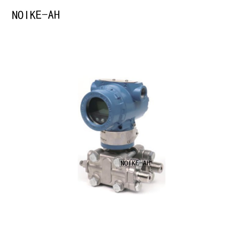
A 4-wire transmitter features completely isolated power supply circuits and signal output circuits, common in heavy-duty or specialized industrial applications.
Terminal Connection Table
| Transmitter Terminal | Function | Connection Destination |
| Power + | Supply Positive | External Power (+) |
| Power – | Supply Negative | External Power (-) |
| Signal + | 4–20mA Output (+) | PLC Analog Input (+) / AI+ |
| Signal – | 4–20mA Output (-) | PLC Analog Input (-) / AI- |
PLC Configuration and Scaling Matrix
PLC analog modules capture raw digital values (e.g., 0–27648 for Siemens or 0–32767 for Rockwell) that correspond to the 4–20mA input. You must scale these raw values into engineering units ($bar, MPa, psi$) within your PLC or HMI software.
Linear Scaling Formula
$$Pressure = LRV + \frac{I – 4}{16} \times (URV – LRV)$$
Where LRV is Lower Range Value, URV is Upper Range Value, and I is the actual loop current.
Troubleshooting Common 4–20mA Loop Faults
If you experience issues during commissioning, isolate the transmitter from the PLC input and use a digital multimeter or loop calibrator to test the loop current directly.
| Symptom / Problem | Potential Root Cause | Recommended Action |
| PLC reads 0 or Under-range | Broken wire, missing 24VDC, or reversed polarity. | Verify 24VDC voltage at the transmitter terminals. |
| PLC reads Full-scale / Maximum | Wrong PLC input mode (set to voltage instead of current) or shorted signal line. | Check PLC channel hardware toggles and software configuration. |
| Fluctuating / Jumping readings | EMI Noise, VFD interference, or improper grounding. | Use shielded twisted-pair cables; ensure shield is grounded at one end only. |
| Current cannot reach 20mA | Insufficient loop voltage or excessive circuit resistance load. | Upgrade power supply capacity or reduce cable distance. |
Industrial Applications: The NOIKE-AH Solution
In professional fluid control, constant pressure water supply, and pump automation systems, pairing high-performance hardware maximizes system reliability.
The NOIKE-AH Pressure Series provides a robust Ecosystem tailored for modern control panels:
- Continuous Feedback: NOIKE-AH pressure transmitters deliver highly accurate 4–20mA, HART, or Modbus signals for real-time PLC/VFD regulation.
- Safety & Interlocking: NOIKE-AH intelligent pressure switches act as localized hardware backups for dry-run protection and emergency high/low pressure cutoffs.
- Local Verification: NOIKE-AH digital pressure gauges provide on-site readouts to quickly verify and calibrate PLC scaling values during maintenance.
Using this integrated approach reduces cabinet troubleshooting time, eliminates signal drift, and ensures stable VFD frequency control.



