
how to increase oval gear flow meter flow range ? A Practical Guide to Flow Range and Sizing
Direct Answer
If by “increasing the parameters” of an oval gear flow meter you mean measuring a higher actual flow rate, this normally cannot be achieved simply by changing the display or software settings.
An oval gear flow meter is a positive displacement flow meter. Its actual measuring capacity is determined by factors such as meter size, measuring chamber volume, gear design, allowable gear speed, liquid viscosity, pressure drop, and the manufacturer’s specified flow range.
If a higher actual flow rate needs to be measured, the usual solution is to select a larger or more suitable flow meter rather than simply changing the range displayed by the transmitter.
If the requirement is only to increase the 4–20 mA output range, pulse scaling, or displayed engineering range, this is an instrumentation configuration issue. However, changing these parameters does not increase the physical measuring capacity of the flow meter.
Key Takeaways
- Increasing the displayed range is not the same as increasing the actual flow capacity.
- If the actual process flow exceeds the rated range of the existing meter, the flow meter should be reselected.
- A higher flow range is generally related to meter size and internal measuring structure.
- Liquid viscosity affects the applicable flow range and pressure drop of an oval gear flow meter.
- Changing the pulse factor, display range, or 4–20 mA scaling only changes how the measurement is represented or transmitted. It does not increase the physical capacity of the meter.
- Proper sizing should consider minimum flow, normal flow, maximum flow, viscosity, temperature, pressure, and connection size.
What Is an Oval Gear Flow Meter?
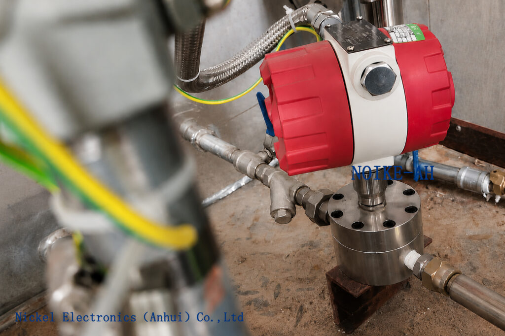
An oval gear flow meter is a type of positive displacement (PD) flow meter.
It typically consists of two intermeshing oval gears installed inside a precision measuring chamber. As liquid enters the meter, the pressure difference between the inlet and outlet causes the gears to rotate.
Each rotation of the gears displaces a defined volume of liquid from the inlet side to the outlet side.
The basic measurement principle can be expressed as:
Flow Rate = Displacement per Unit Time × Gear Rotation
A sensor detects the rotation of the gears and generates pulse signals. The electronic system then uses the pulse signal and calibrated pulse factor to calculate instantaneous and totalized flow.
Because the measurement is based on a defined volume, oval gear flow meters are widely used for liquids such as oils, lubricants, hydraulic fluids, fuels, and other relatively clean liquids.
What Does “Increasing the Parameters” Actually Mean?
The phrase “increase the parameters” can refer to several different requirements.
Understanding the difference is important before modifying or replacing an oval gear flow meter.
1. Increasing the Maximum Flow Rate
For example, the existing flow meter may have a range of:
1–20 L/min
while the actual process requires:
5–50 L/min
In this case, simply changing the maximum value on the display from 20 to 50 L/min is not an appropriate solution.
The internal gears, measuring chamber, flow passages, and mechanical components are designed for a specific operating range.
If the actual flow exceeds the specified range, several problems may occur:
- Excessive gear speed
- Increased pressure drop
- Increased mechanical wear
- Changes in measurement performance
- Pulse frequency exceeding the capability of downstream equipment
- Reduced long-term reliability
Therefore, when the actual process flow needs to be increased significantly, a suitable larger-capacity flow meter should normally be selected.
Different sizes of oval gear flow meters are designed for different flow ranges. This means that the actual flow capacity is closely related to the meter’s mechanical design and specification.
2. Increasing the Flow Meter Size
If the existing flow meter is too small for the actual process flow, a larger-size oval gear flow meter may be required.
For example:
DN25 → DN40 → DN50 → DN80
However, it is important to understand that:
A larger pipe size does not automatically mean that a larger oval gear flow meter is required.
Flow meter sizing should not be based on pipe diameter alone.
The following parameters should also be considered:
- Minimum flow rate
- Normal flow rate
- Maximum flow rate
- Liquid viscosity
- Operating pressure
- Operating temperature
- Allowable pressure drop
- Required accuracy
- Connection standard
The selected flow meter should operate within an appropriate range under the actual process conditions.
3. Increasing the Displacement per Revolution
Another possible meaning of “increasing the parameter” is increasing the amount of liquid displaced by the gears during each revolution.
This is related to the internal measuring volume and gear design.
The relationship can be simplified as:
Gear Rotation → Displacement → Pulse Output → Flow Calculation
The displacement per revolution is determined by the physical design of the gears and measuring chamber.
Therefore, changing the gear size or measuring chamber is not equivalent to changing a software parameter.
If the internal displacement needs to be increased, the gear geometry, measuring chamber, clearances, shaft structure, and sensor configuration may all need to be considered.
This is normally a flow meter design or model-selection issue, rather than a field adjustment.
4. Increasing the 4–20 mA Output Range
This situation is different.
For example, suppose the actual flow meter is capable of measuring:
0–100 L/min
but the transmitter is configured as:
4–20 mA = 0–50 L/min
Depending on the transmitter design and allowable configuration range, the output scaling may be adjusted.
However, an important distinction must be made:
Changing the 4–20 mA range does not increase the physical measuring capacity of the flow meter.
It only changes the relationship between:
Actual Flow → Output Signal
Therefore, before changing the output range, verify:
- The actual measuring range of the flow meter
- Sensor output type
- Pulse factor or K-factor
- Transmitter configuration range
- PLC/DCS input range
- Engineering units used by the control system
How Does the Flow Range of an Oval Gear Flow Meter Work?
The flow range of an oval gear flow meter is not an unlimited software parameter.
The measurement process can be simplified as:
Actual Flow → Gear Rotation → Sensor Pulses → Transmitter Calculation → Display/Output
The mechanical section at the beginning of this chain determines how much actual flow the meter can physically handle.
Different models and sizes may therefore have different flow ranges.
For example:
| Meter Size | Typical Application |
|---|---|
| Small-size models | Low flow applications |
| Medium-size models | Medium flow applications |
| Large-size models | Higher flow applications |
The specific flow range must always be checked against the manufacturer’s datasheet and the actual process conditions.
Therefore, when someone asks how to “make the parameters larger,” the correct engineering approach is usually:
Review the application → Recalculate the required flow range → Select a suitable meter size/model
rather than simply changing a numerical value in the display.
Key Parameters to Check Before Increasing the Flow Range
1. Maximum Flow Rate
The first step is to determine the actual maximum process flow.
For example:
- Minimum flow: 5 L/min
- Normal flow: 20 L/min
- Maximum flow: 40 L/min
The selected flow meter must be capable of operating at the maximum required flow.
The selection should not be based only on the normal flow rate.
2. Minimum Flow Rate
Do not focus only on the maximum flow.
If an oversized flow meter is selected, it may handle the maximum flow easily but operate near the lower end of its effective measuring range during normal operation.
Therefore, the following three values should normally be considered together:
Qmin + Qnormal + Qmax
A suitable flow meter should provide an appropriate measurement range across the actual operating conditions.
3. Liquid Viscosity
Viscosity is particularly important when selecting an oval gear flow meter.
Typical applications may include:
- Hydraulic oil
- Lubricating oil
- Fuel oil
- Gear oil
- Resin
- Adhesive
- Other viscous liquids
Different viscosities can affect:
- Pressure drop
- Leakage characteristics
- Operating speed
- Applicable flow range
- Measurement performance
If the viscosity changes significantly with temperature, the viscosity at the actual operating temperature should also be considered.
Therefore:
The flow range of an oval gear flow meter should not be evaluated without considering liquid viscosity.
How to Select a Larger Oval Gear Flow Meter
If the existing flow meter does not provide a sufficiently large flow range, the following selection process can be used.
Step 1: Determine the Actual Flow Range
First determine:
Qmin / Qnormal / Qmax
Avoid providing only one flow value.
For example:
Minimum flow: 5 L/min
Normal flow: 20 L/min
Maximum flow: 40 L/min
This information provides a much better basis for selecting the meter.
Step 2: Confirm the Liquid
Provide the exact liquid being measured.
For example:
- Hydraulic oil
- Lubricating oil
- Diesel
- Water
- Chemical liquid
- Resin
The liquid type affects material compatibility, viscosity, pressure loss, and the suitability of the meter design.
Step 3: Confirm Viscosity
For oil or high-viscosity liquids, provide the viscosity whenever possible:
Viscosity = XX mPa·s / cP
If viscosity changes with temperature, also provide:
Operating temperature + viscosity at operating temperature
This information is particularly important for positive displacement flow meter selection.
Step 4: Check Pressure and Temperature
Confirm:
- Maximum operating pressure
- Normal operating pressure
- Minimum operating temperature
- Maximum operating temperature
The selected flow meter must satisfy the pressure and temperature requirements of the application in addition to the flow range.
Step 5: Check Pipe Size and Connection
Finally, confirm:
- Pipe size
- Connection type
- Thread or flange standard
- Wetted material requirements
Pipe size should be considered together with the actual process flow rather than used as the only sizing criterion.
Can You Simply Change the Gear Size?
In general, the gears of an oval gear flow meter should not be modified in the field.
The gears, measuring chamber, shaft, seals, and sensor system are designed as an integrated measurement system.
Changing the gear structure may affect:
- Displacement per revolution
- Internal clearance
- Leakage characteristics
- Pressure drop
- Gear speed
- Pulse factor
- Measurement accuracy
- Mechanical service life
Therefore, if a significantly higher flow range is required, the preferred approach is to select a suitable larger-capacity model or have the manufacturer evaluate a customized design.
Common Problems When Trying to Increase Flow Range
Problem 1: Simply Changing the Display Range
Suppose the flow meter has a specified maximum flow of:
20 L/min
but the display is changed to:
0–50 L/min
The display may be capable of showing a value of 50 L/min, but this does not mean that the flow meter itself is mechanically capable of measuring 50 L/min.
The display range and the physical measuring range are two different concepts.
Problem 2: Ignoring Viscosity
The same flow meter can have different operating characteristics with liquids of different viscosities.
For this reason, it is not sufficient to say:
“This flow meter can measure up to 50 L/min.”
The application conditions should also specify the liquid and its viscosity.
Problem 3: Selecting a Larger Meter Only Because the Pipe Is Larger
A larger pipe does not automatically mean that a larger flow meter is the best choice.
If the actual flow is relatively low, an oversized flow meter may operate near the lower end of its effective measuring range.
The selection should therefore consider:
Minimum Flow + Normal Flow + Maximum Flow
rather than pipe diameter alone.
Problem 4: Increasing Flow Without Checking Pressure Drop
When the flow rate increases, pressure drop must also be evaluated.
This is particularly important for high-viscosity liquids.
Therefore, when increasing the required flow range, do not consider only:
Flow Range
Also evaluate:
Pressure Drop
Applications
Oval gear flow meters are commonly used for liquid measurement applications where positive displacement measurement is appropriate.
Typical applications include:
- Hydraulic oil measurement
- Lubricating oil measurement
- Fuel measurement
- Chemical liquid dosing
- Resin and adhesive measurement
- Industrial oil transfer
- Process liquid measurement
- Liquid batching systems
They are particularly useful for relatively clean liquids and many oil-based applications where direct volumetric measurement is required.
Recommended Instrument: Oval Gear Flow Meter
If you are experiencing the following problem:
“The flow range of my existing oval gear flow meter is too small. How can I make the parameters larger?”
Do not immediately change the displayed range.
First confirm the following application information:
| Parameter | Required Information |
|---|---|
| Medium | What liquid is being measured? |
| Minimum Flow | Qmin |
| Normal Flow | Qnormal |
| Maximum Flow | Qmax |
| Viscosity | mPa·s / cP |
| Temperature | °C |
| Pressure | MPa / bar |
| Pipe Size | DN / inch |
| Connection | Thread / Flange / Tri-Clamp |
| Output | Pulse / 4–20 mA / RS485 |
| Accuracy | Required accuracy |
Once these parameters are available, it becomes possible to determine whether the application requires:
Output parameter adjustment
or
A larger/suitable oval gear flow meter.
FAQ
1. Can I increase the maximum flow rate of an oval gear flow meter by changing its parameters?
Generally, no.
The actual measuring range is determined by the mechanical design and rated specifications of the flow meter. If the required flow exceeds the specified range, the flow meter should be properly reselected.
2. If I increase the 4–20 mA range, will the actual flow range of the flow meter increase?
No.
Changing the 4–20 mA scaling changes the relationship between the measured flow and the output signal. It does not increase the physical measuring capacity of the flow meter.
3. If the pipe size increases, do I need a larger oval gear flow meter?
Not necessarily.
Flow meter size should be selected based on the actual minimum, normal, and maximum flow rates, together with viscosity, pressure, temperature, and other application conditions.
4. Why can oval gear flow meters with the same nominal connection size have different flow ranges?
Different products can have different gear geometries, measuring chamber designs, internal clearances, sensor configurations, and operating specifications.
Therefore, the same nominal connection size does not necessarily mean that two flow meters have the same flow range.
5. Can a larger flow meter be used to increase the flow rate of a high-viscosity liquid?
It may be possible, but the application must be evaluated based on the actual viscosity, temperature, pressure, required flow rate, and allowable pressure drop.
A larger meter should not be selected simply on the assumption that a larger size always provides better performance.
Conclusion
The question “How can I increase the parameters of an oval gear flow meter?” needs to be clarified first because “parameter” can refer to several different things.
If you want to increase:
Display range
→ Check the transmitter or display configuration.
4–20 mA output range
→ Check the output scaling and system configuration.
Actual maximum flow rate
→ Recalculate the application and select a suitable flow meter.
Displacement per revolution
→ This involves the gear and measuring chamber design and normally requires manufacturer evaluation.
Meter size
→ Select the appropriate meter based on actual flow conditions rather than pipe diameter alone.
Therefore, for an oval gear flow meter, the correct way to increase the actual measurable flow range is normally not to simply change a parameter. Instead, the flow meter should be selected according to the required flow range, meter size, internal displacement, liquid viscosity, pressure, temperature, pressure drop, and output requirements.
RFQ CTA
Are you selecting an oval gear flow meter with a larger flow range?
Provide the following information:
Medium + Flow Range + Viscosity + Temperature + Pressure + Pipe Size + Output
NOIKE-AH can help evaluate the application and identify a suitable oval gear flow meter specification, flow range, and output configuration.



