
Radar Level Gauge Selection Guide: Frequency, Antenna & Installation Introduction
Selecting a radar level gauge is not simply a matter of choosing the highest frequency or the longest measuring range. Reliable radar level measurement depends on multiple factors, including radar frequency, antenna design, measured medium, dielectric constant, tank geometry, installation position, measuring range, temperature, and pressure.
For engineers selecting a radar level transmitter for a storage tank, process vessel, silo, or other industrial equipment, the most important question is:
Does the radar frequency, antenna, and installation method match the actual process conditions?
Common frequencies used in modern non-contact radar level measurement include 6 GHz, 26 GHz, and 80 GHz. Higher frequency can generally provide a narrower beam angle, but this does not mean that a higher-frequency radar is always the best solution.
Actual radar performance depends on the combined effect of frequency, beam angle, antenna configuration, installation conditions, and the dielectric properties of the measured medium.
Therefore, radar level gauge selection should be treated as a systematic, application-based engineering process.
1. What Is a Radar Level Gauge?
A radar level gauge, also known as a radar level transmitter or radar level sensor, measures the distance to the material surface by transmitting electromagnetic waves and receiving the reflected signal from the surface.
In a typical non-contact radar level measurement system:
- The radar antenna transmits a radar signal toward the material surface.
- The signal reaches the surface and is reflected.
- Part of the reflected signal returns to the antenna.
- The electronic system calculates the distance based on the signal’s travel time.
- The instrument calculates the actual level based on the tank reference point and the measured distance.
For a time-of-flight (TOF) measurement system:
Distance = c × t / 2
Where:
- c = propagation speed of the electromagnetic wave
- t = round-trip travel time of the radar signal
- 2 = the signal travels to the target and back
Because radar level gauges do not need to physically contact the measured medium, they are particularly suitable for corrosive, dirty, high-temperature, or otherwise demanding process conditions.
2. Radar Frequency: 6 GHz, 26 GHz, and 80 GHz
Radar frequency is one of the first parameters to consider when selecting a radar level gauge.
However, frequency should not simply be interpreted as “higher is better.”
The appropriate frequency should be selected based on the tank geometry, medium characteristics, and installation conditions.
2.1 6 GHz Radar
Compared with higher-frequency radar, lower-frequency radar generally has a relatively wider beam.
It can be considered for:
- Storage tanks with relatively simple geometry
- Applications where a wider beam is acceptable
- Stilling well applications
- Bypass chamber applications
- Certain level measurement applications requiring specific signal propagation characteristics
For example, in stilling well or bypass applications, the beam characteristics of lower-frequency radar may provide certain advantages.
However, because the beam is relatively wider, tank walls, internal pipes, ladders, support structures, and other objects may affect the measurement signal if the instrument is not installed correctly.
2.2 26 GHz Radar
26 GHz radar is widely used for industrial liquid and solid level measurement.
It can be applied to:
- Industrial liquids
- Slurries
- Certain challenging process media
- Conventional storage tanks
- Process vessels
- Certain high-temperature and high-pressure applications
26 GHz radar can provide a practical balance of performance for many industrial applications.
Where the tank geometry is moderately complex and a more focused beam than lower-frequency radar is desirable, while maintaining good application flexibility, 26 GHz can be a suitable option.
2.3 80 GHz Radar
80 GHz radar has become increasingly common in industrial level measurement.
One of its major advantages is its ability to provide a narrower radar beam.
A narrow beam can help focus the radar signal toward the material surface and reduce the possibility of interference from tank walls and internal structures.
80 GHz radar can be particularly attractive for:
- Tall and narrow tanks
- Tanks with internal pipes or support structures
- Applications requiring a narrow radar beam
- Small vessels
- Applications with limited installation space
However, it is important to understand that:
80 GHz does not automatically mean it is the best choice for every application.
The selection should still consider:
- Measured medium
- Dielectric constant
- Vapor
- Condensation
- Foam
- Tank geometry
- Antenna type
- Installation method
3. Quick Radar Frequency Selection Guide
| Application Condition | Selection Direction |
|---|---|
| Simple storage tank | Consider 6 / 26 / 80 GHz according to the actual application |
| Narrow tank or significant internal obstructions | 26 or 80 GHz may be considered |
| Stilling well / bypass chamber | Select according to pipe geometry and antenna design |
| Small vessel | The narrow beam of 80 GHz may be advantageous |
| Applications with significant vapor | Evaluate the medium, frequency, and antenna together |
| Foam or low-reflectivity medium | Evaluate dielectric constant, foam characteristics, and antenna |
| Highly corrosive medium | Select antenna materials according to chemical compatibility |
| High-temperature / high-pressure service | Verify the temperature and pressure ratings of the complete instrument and antenna |
Note: This table is intended as a general selection reference and is not a universal rule. Final selection should be based on the specific application and the manufacturer’s technical and installation requirements.
4. Antenna Selection: Why Is the Antenna Important?
The antenna is an important interface between the radar electronics and the actual process environment.
The antenna directly affects:
- Radar beam shape
- Beam angle
- Signal concentration
- Compatibility with the process medium
- Resistance to buildup and condensation
- Installation method
- Suitability for stilling wells or bypass chambers
In general, where the design permits, a larger antenna can provide higher antenna gain and help concentrate the radar signal, which can be beneficial when detecting weak surface echoes.
However:
A larger antenna is not automatically better.
The antenna size must be compatible with:
- Tank connection
- Flange size
- Tank nozzle
- Stilling well
- Bypass chamber
- Process temperature and pressure
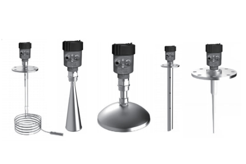
5. Common Radar Antenna Types
5.1 Horn Antenna
The horn antenna is one of the common antenna configurations used in industrial radar level measurement.
Typical characteristics include:
- Good directional performance
- Suitable for various liquid applications
- Available in different sizes
- Depending on the design, suitable for high-temperature and high-pressure applications
When selecting a horn antenna, particular attention should be paid to:
- Antenna diameter
- Beam angle
- Nozzle dimensions
- Installation height
- Process temperature
- Process pressure
5.2 Rod Antenna
Rod antennas can be considered for applications where a compact antenna configuration is required.
They may be suitable for:
- Small storage tanks
- Space-limited applications
- Certain corrosive media
- Applications requiring specific antenna materials
For corrosive media, the chemical compatibility between the antenna/sealing materials and the actual medium must be confirmed.
A material should not be considered suitable for all corrosive media simply because it is described as “corrosion resistant.”
5.3 Parabolic Antenna
A parabolic antenna can produce a highly directional radar beam.
It can be considered for applications requiring strong signal focusing.
Such antennas may be used in certain industrial radar level measurement and tank gauging applications.
However, the parabolic antenna should not be selected independently of:
- Tank geometry
- Installation position
- Measuring distance
- Measured medium
5.4 PTFE / Process-Sealed Antenna
For highly corrosive media, an antenna with a suitable PTFE or other chemically compatible material can be considered.
The key consideration is:
Whether the material directly exposed to the process medium is chemically compatible with the actual medium.
Material compatibility should be evaluated based on:
- Medium type
- Concentration
- Temperature
- Pressure
6. Radar Level Gauge Installation: Key Considerations
Even when the radar instrument’s specifications are suitable for the application, an improper installation position can result in unstable measurement.
Therefore:
Installation is just as important as frequency and antenna selection.
6.1 Avoid Installing Directly Above the Filling Point
In general, the radar should not be installed so that its beam points directly toward the filling location.
The filling process may generate:
- Liquid turbulence
- Foam
- Material splashing
- An unstable surface
These conditions can cause unstable radar echoes.
Therefore, the radar should preferably be installed away from obvious filling streams.
6.2 Avoid Directly Targeting Internal Obstacles
The radar beam should have a clear path between the antenna and the material surface whenever possible.
Particular attention should be paid to:
- Internal pipes
- Ladders
- Support structures
- Agitators
- Heating coils
- Tank walls
- Nozzle structures
Modern radar instruments may provide false-echo suppression and echo-processing functions.
However:
Software filtering should not be considered a substitute for proper mechanical installation.
Correct installation remains the foundation for stable measurement.
7. Radar Beam Angle and Tank Geometry
The relationship between the radar beam angle and tank geometry is critical.
If the radar beam is relatively wide, the probability of the signal encountering tank walls or internal structures increases.
A narrower radar beam can reduce this effect.
This is one reason why 80 GHz radar can provide advantages in certain complex vessels.
However:
The actual beam characteristics are not determined by frequency alone.
Antenna type, antenna size, and the specific instrument design also affect the final beam characteristics.
Before finalizing the radar selection, it is recommended to collect:
- Tank diameter
- Tank height
- Nozzle diameter
- Nozzle height
- Internal obstructions
- Filling point location
- Agitator location
- Required measuring range
- Medium characteristics
- Operating temperature and pressure
8. Nozzle Design and Installation
The nozzle is an often-overlooked factor in radar level gauge installation.
If the nozzle is too long or has an unsuitable configuration, it may affect the radar signal and create additional echoes.
Depending on the radar design:
- The antenna may need to extend beyond the nozzle.
- Certain antennas may be installed inside the nozzle.
- Some models have specific nozzle-length limitations.
Therefore:
The maximum allowable nozzle length cannot be determined simply from the radar frequency.
The allowable nozzle dimensions depend on the specific:
- Radar model
- Antenna type
- Antenna size
- Process connection
- Installation configuration
The final installation should always be checked against the installation manual for the specific product.
9. When Should a Stilling Well Be Used?
A stilling well or bypass chamber can be considered when free-space radar measurement is difficult.
Typical applications include:
- Storage tanks with significant surface turbulence
- Vessels with complicated internal structures
- Applications requiring a relatively controlled measurement path
- Certain tank gauging applications
A stilling well can provide a more controlled path for the radar signal and reduce the influence of surrounding structures.
However, the radar antenna must be compatible with the:
- Internal diameter
- Length
- Installation configuration
of the stilling well.
Therefore, stilling-well applications should not simply use the same installation rules as open-vessel installations.
10. Measured Medium: Why Does Dielectric Constant Matter?
Radar signal reflection is closely related to the electrical properties of the measured material.
One important parameter is the relative dielectric constant (εr or DK).
In general:
- Materials with a higher dielectric constant can produce stronger radar reflections.
- Materials with a lower dielectric constant may produce weaker radar echoes.
Therefore, radar level gauge selection should consider:
- Liquid or solid
- Relative dielectric constant
- Foam
- Dust
- Vapor
- Condensation
- Surface turbulence
- Product buildup
This is why simply asking:
“Which is better, 26 GHz or 80 GHz?”
is not sufficient to complete a proper radar selection.
11. Foam, Vapor, and Condensation
Foam and condensation can reduce radar signal quality or create additional reflections.
The following applications require particular attention:
- Wastewater treatment
- Chemical storage tanks
- Mixing tanks
- Biological processes
- Steam-generating processes
- High-temperature liquids
- Media that easily generate vapor layers
In these applications, the complete measurement system should be evaluated rather than focusing only on radar frequency.
The following factors may be more important than simply choosing a higher frequency:
- Appropriate antenna design
- Correct installation position
- Signal-processing capability
12. Radar Level Measurement for Solids
Radar technology can also be used for level measurement of bulk solids, including:
- Powders
- Granules
- Aggregates
- Raw materials
- Stored bulk materials
However, solid materials can introduce additional challenges:
- Irregular material surfaces
- Dust
- Filling streams
- Low dielectric constant
- Changing material angles
- Multiple reflections
Therefore, the radar level gauge should be selected according to the actual silo geometry and material characteristics.
If the silo contains multiple internal structures or the radar needs to target a specific area, a narrower radar beam may provide significant advantages.
13. Radar Level Gauge Selection Checklist
Before purchasing a radar level transmitter, it is recommended to collect the following information.
Process Medium
- Measured medium
- Liquid or solid
- Relative dielectric constant, if known
- Minimum level
- Maximum level
- Normal operating level
- Presence of foam
- Presence of dust
- Vapor or condensation
- Corrosiveness
Tank Parameters
- Tank diameter
- Tank height
- Tank shape
- Nozzle diameter
- Nozzle height
- Internal pipes
- Agitator
- Heating coils
- Ladders or support structures
- Filling point location
- Outlet location
Process Conditions
- Maximum operating temperature
- Minimum operating temperature
- Operating pressure
- Maximum pressure
- Vacuum conditions, if applicable
- Hazardous area classification
- Explosion-proof certification requirements
Instrument Requirements
- Radar frequency
- Antenna type
- Antenna material
- Process connection
- Measuring range
- Accuracy requirement
- Output signal
- Communication protocol
- Display requirement
- Required certifications
14. Common Radar Level Gauge Selection Mistakes
Mistake 1: Choosing 80 GHz Simply Because the Frequency Is Higher
A higher frequency does not necessarily provide better measurement performance in every application.
Proper selection should consider:
Frequency + Antenna + Medium + Installation Conditions + Tank Geometry
Mistake 2: Ignoring the Antenna
Even if two radar instruments operate at the same frequency, their performance may differ.
Possible reasons include:
- Different antenna designs
- Different antenna sizes
- Different beam angles
- Different process connections
Mistake 3: Ignoring the Nozzle
If the radar is installed on an unsuitable nozzle, it may cause:
- Additional echoes
- Dead zones
- Signal interference
- Unstable measurement
Therefore, nozzle dimensions and configuration must be included in the selection process.
Mistake 4: Installing Directly Above the Filling Stream
Turbulence, foam, and splashing caused by the filling process can cause the radar echo to fluctuate.
Mistake 5: Ignoring Internal Tank Structures
A tank may appear unobstructed from the outside, while internally it may contain:
- Pipes
- Heating coils
- Ladders
- Supports
- Agitators
If these structures are located within the radar beam, they may generate interfering echoes.
Mistake 6: Selecting Only According to Maximum Measuring Range
A radar product with a long advertised maximum measuring distance does not necessarily achieve that distance under every actual process condition.
Actual measurement performance can also be affected by:
- Medium
- Dielectric constant
- Antenna
- Installation
- Tank geometry
15. Practical Radar Level Gauge Selection Process
Radar level gauge selection can be simplified into five steps.
Step 1: Define the Process Conditions
Determine:
- Measured medium
- Dielectric properties
- Temperature
- Pressure
- Foam
- Vapor
- Dust
- Corrosiveness
Step 2: Define the Vessel Geometry
Record:
- Tank dimensions
- Nozzle dimensions
- Nozzle height
- Internal structures
- Filling location
- Agitator location
Step 3: Select the Radar Frequency
Compare:
6 GHz, 26 GHz, and 80 GHz
based on the actual application rather than simply selecting the highest frequency.
Step 4: Select the Antenna
Match the antenna according to:
- Antenna type
- Antenna size
- Material
- Medium
- Tank geometry
- Process conditions
Step 5: Confirm the Installation
Check:
- Whether the radar beam has a clear path
- Whether the nozzle dimensions are suitable
- Whether the wall clearance is adequate
- Whether the radar is away from the filling point
- Whether a stilling well or bypass chamber is required
- Whether the installation meets the requirements of the specific radar model
16. Conclusion: How to Select the Right Radar Level Gauge
The most suitable radar level gauge is not necessarily the product with the highest frequency, longest measuring range, or highest advertised accuracy.
A technically sound radar selection should consider the complete measurement system:
Frequency + Antenna + Measured Medium + Tank Geometry + Installation Method + Process Conditions
For simple storage tanks, several radar configurations may be capable of meeting the measurement requirements.
However, for challenging applications involving:
- Narrow tanks
- Internal obstructions
- Foam
- Vapor
- Dust
- Low-dielectric media
- High-temperature or high-pressure conditions
the radar selection should be evaluated specifically according to the actual application.
The most reliable approach is to provide the radar level gauge manufacturer with:
Measured medium + Tank dimensions + Nozzle dimensions + Measuring range + Temperature + Pressure + Dielectric constant, if known + Tank installation drawing
before finalizing the model.
When the radar frequency, antenna, and installation method are correctly matched to the actual process conditions, non-contact radar level measurement can provide stable, reliable, and low-maintenance level measurement for industrial storage tanks, process vessels, silos, and other level measurement applications.
FAQ: Frequently Asked Questions About Radar Level Gauge Selection
Is 80 GHz radar always better than 26 GHz radar?
No.
80 GHz radar offers the advantage of a narrower beam and may be more suitable for applications with limited space or internal tank obstructions.
However, final performance still depends on:
- Frequency
- Antenna
- Installation method
- Measured medium
- Tank geometry
Therefore, radar quality and suitability should not be judged solely by frequency.
What is the most important parameter when selecting a radar level gauge?
There is no single parameter that is most important for every application.
The key factors normally include:
Measured medium, dielectric properties, tank geometry, measuring range, antenna configuration, and installation conditions.
Can radar level gauges measure liquids with foam?
Yes.
However, actual measurement performance depends on:
- Foam characteristics
- Dielectric constant
- Antenna
- Radar instrument design
- Installation conditions
For applications with significant foam, detailed process information should be provided during the selection stage.
Can radar level gauges measure solid materials?
Yes.
Radar level technology can be used for powders, granules, and other bulk solid materials.
However, the following factors should be carefully evaluated:
- Dust
- Irregular material surfaces
- Low dielectric constant
- Filling conditions
- Internal silo structures
Does a radar level gauge need to contact the measured medium?
No.
A conventional non-contact radar level gauge is normally installed above the tank or vessel and uses electromagnetic waves to measure the position of the material surface without direct contact with the medium.
This is one of the key advantages of radar level measurement for corrosive, dirty, high-temperature, and other demanding applications.
What information should I provide when requesting a radar level gauge quotation?
At minimum, provide:
Measured medium, tank diameter and height, measuring range, nozzle size and height, operating temperature, operating pressure, dielectric constant if known, and information about internal tank obstructions.
If a tank drawing or installation drawing is available, providing it can help the manufacturer evaluate the appropriate radar frequency, antenna, and installation configuration more accurately.



