
Introduction
A water flow switch is a critical component in many automatic fire sprinkler systems. When water begins to flow through the sprinkler piping because a sprinkler has operated, the flow switch detects the predetermined flow and sends an electrical signal to the fire alarm system.
However, one common mistake is to assume that NFPA 72 alone defines all requirements for sprinkler-system flow switches.
In practice, several NFPA standards work together:
- NFPA 13 — addresses the installation of automatic sprinkler systems, including waterflow alarm devices.
- NFPA 72 — addresses fire alarm and signaling systems, including waterflow alarm-initiating devices and their connection to fire alarm systems.
- NFPA 25 — addresses inspection, testing, and maintenance of water-based fire protection systems.
- Other adopted building, fire, electrical, and local regulations may also apply depending on the project and jurisdiction.
NFPA itself identifies a sprinkler waterflow alarm-initiating device as an attachment to the sprinkler system that detects predetermined water flow and can initiate an alarm condition through a fire alarm system or operate an associated local alarm or other function.
Understanding which standard applies to each part of the system is essential when selecting, installing, testing, or specifying a fire sprinkler flow switch.
What Is a Flow Switch in a Fire Sprinkler System?
A water flow switch, also called a sprinkler waterflow alarm-initiating device, detects water movement within a sprinkler system.
A typical mechanical waterflow switch uses a vane or similar sensing mechanism installed in the sprinkler piping. When sufficient water flow occurs, the sensing mechanism moves and operates an electrical switch.
The resulting signal can be transmitted to a fire alarm control unit, which can then process the signal as an alarm condition according to the system design.
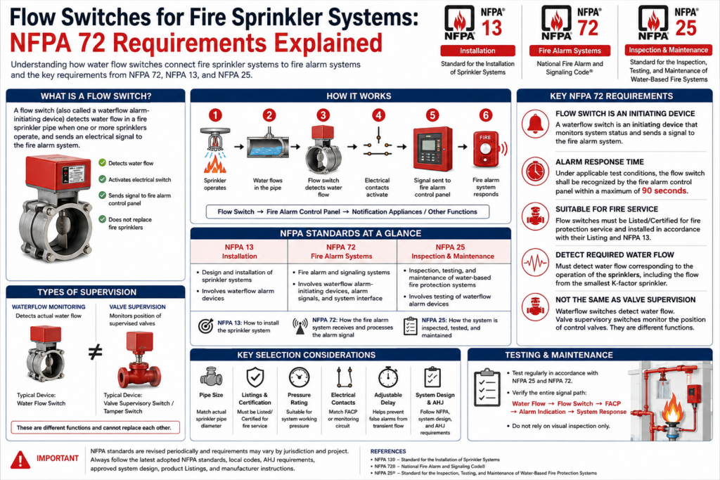
The basic sequence is:
Sprinkler operates → Water flows → Flow switch detects flow → Electrical contact changes state → Fire alarm control unit receives alarm signal → Alarm/notification functions operate
The flow switch therefore does not replace the sprinkler itself. Its function is to detect the hydraulic consequence of sprinkler operation and initiate the appropriate alarm signal.
Does NFPA 72 Require a Flow Switch on Every Sprinkler System?
This question requires some care.
NFPA 72 is primarily the National Fire Alarm and Signaling Code, rather than the installation standard for automatic sprinkler piping. NFPA’s own description states that NFPA 72 provides safety provisions for fire alarms and signaling systems.
Therefore, the question of whether a particular sprinkler system must have a waterflow alarm device should not be answered by looking at NFPA 72 alone.
The applicable requirements may come from:
- NFPA 13;
- The building or fire code adopted by the jurisdiction;
- NFPA 72 where a fire alarm or sprinkler monitoring system is provided;
- The requirements of the authority having jurisdiction (AHJ);
- The approved system design.
For this reason, manufacturers should avoid marketing language such as:
“NFPA 72 requires every sprinkler system to use this specific flow switch.”
That statement is too broad.
A technically safer statement is:
Waterflow alarm-initiating devices used as part of a fire alarm or sprinkler monitoring system are subject to applicable NFPA 72 requirements, while sprinkler-system installation requirements are addressed by the applicable edition of NFPA 13 and local codes.
Key NFPA 72 Requirements for Water Flow Switches
1. The Flow Switch Functions as an Initiating Device
One of the most important concepts in NFPA 72 is the distinction between an initiating device and a notification appliance.
A sprinkler waterflow device detects a condition and provides an input to the fire alarm system. It is therefore part of the initiating side of the system.
NFPA technical committee documentation for the 2025 edition identifies the sprinkler waterflow alarm-initiating device within the fire alarm initiating-device framework. The documentation also identifies common terminology such as “waterflow switch,” “waterflow device,” and “waterflow detection device.”
This distinction is important because the flow switch itself does not necessarily provide the final occupant notification.
The system architecture may look like:
Waterflow switch → Fire alarm control unit → Notification appliances / supervising station
The exact system configuration depends on the project requirements and adopted codes.
2. Waterflow Signal Must Be Recognized Within the Required Time
One of the most frequently discussed NFPA 72 requirements for sprinkler waterflow switches is the alarm response time.
For waterflow switches, NFPA 72 includes requirements addressing the maximum allowable delay between waterflow switch activation and recognition of the alarm signal at the fire alarm control unit.
For the 2025 edition of NFPA 72, testing guidance identifies 90 seconds as the maximum time for a waterflow switch to produce an alarm at the control unit under the applicable test conditions.
This requirement is important because a waterflow switch should not respond immediately to every minor hydraulic fluctuation.
Sprinkler systems can experience pressure changes, surges, or other transient conditions. The waterflow detection system therefore needs an appropriate mechanism to distinguish sustained sprinkler-system waterflow from short-duration fluctuations.
However, manufacturers should not interpret the 90-second figure as meaning that every flow switch must have a fixed 90-second delay.
The actual delay setting depends on:
- The listed device;
- The fire alarm system;
- The sprinkler system;
- The approved design;
- Applicable code requirements;
- AHJ requirements.
Therefore, 90 seconds should be treated as a maximum response criterion where applicable, not as a recommended standard delay setting for every application.
3. The Flow Switch Must Be Suitable for the Application
A flow switch installed on a fire sprinkler system is not simply an ordinary industrial flow switch.
Fire protection applications have specific listing, installation, supervision, and testing considerations.
NFPA 13 materials addressing waterflow alarm devices state that such devices are to be listed for the service and constructed and installed so that qualifying sprinkler-system waterflow produces the required alarm response.
This is one reason why product selection should begin with the fire-protection listing and system application, rather than simply comparing electrical specifications.
For example, a general industrial flow switch may have:
- A suitable pipe size;
- SPDT contacts;
- High pressure rating;
- Adjustable set point;
- IP protection;
but those specifications alone do not demonstrate suitability for a fire sprinkler application.
4. The Device Must Detect the Required Waterflow
The flow switch must be capable of detecting the waterflow associated with sprinkler operation.
NFPA 13 materials describe the waterflow alarm-device criterion in relation to flow equal to or greater than the flow from a single automatic sprinkler having the smallest K-factor installed in the system.
This is an important design consideration.
A flow switch that is too insensitive may fail to respond to the required sprinkler flow.
A device that is excessively sensitive, or improperly adjusted, may be more susceptible to unwanted operation caused by transient conditions.
Consequently, selection should consider:
- Minimum required flow;
- Pipe diameter;
- Pipe configuration;
- Sprinkler K-factor;
- Flow switch operating characteristics;
- System pressure;
- Required delay;
- Device listing;
- Manufacturer installation instructions.
The correct flow switch is therefore determined by the complete sprinkler-system design, not by pipe diameter alone.
5. Waterflow Alarm Is Different from Valve Supervisory Monitoring
This is another common source of confusion.
A sprinkler system may have both:
Waterflow monitoring
This detects actual water movement through the sprinkler piping.
Typical device:
Water flow switch
Valve supervisory monitoring
This detects whether a supervised control valve has moved away from its normal position.
Typical device:
Valve supervisory/tamper switch
These are different functions.
A waterflow switch answers:
“Is water flowing?”
A valve supervisory switch answers:
“Is the sprinkler control valve in its normal position?”
A complete sprinkler monitoring system may require both functions depending on the applicable codes and system design.
They should therefore not be treated as interchangeable devices.
NFPA 72 vs. NFPA 13 vs. NFPA 25
Understanding the relationship between the three standards is essential for engineers, contractors, distributors, and flow-switch manufacturers.
| Standard | Primary Focus | Flow Switch Relevance |
|---|---|---|
| NFPA 13 | Installation of automatic sprinkler systems | Waterflow alarm devices and sprinkler-system installation |
| NFPA 72 | Fire alarm and signaling systems | Waterflow alarm-initiating devices, alarm signals, interfaces, testing |
| NFPA 25 | Inspection, testing and maintenance of water-based fire protection systems | Periodic inspection and testing of waterflow alarm devices |
NFPA 25 documentation, for example, identifies waterflow alarm devices as equipment requiring periodic testing. Previous NFPA 25 provisions distinguished between mechanical waterflow alarm devices and vane-type or pressure-switch-type waterflow alarm devices.
The 2025 NFPA 25 revision materials also identify waterflow alarms under the inspection/testing requirements of Chapter 13.
This means a manufacturer writing technical documentation should avoid attributing every requirement to NFPA 72.
How a Fire Sprinkler Flow Switch Works
A typical vane-type water flow switch works through a relatively simple mechanical principle.
Step 1: Normal condition
There is no qualifying waterflow through the sprinkler piping.
The sensing mechanism remains in its normal position and the electrical contacts remain in their normal state.
Step 2: Sprinkler activation
When sufficient heat causes a sprinkler to operate, water begins flowing through the piping.
Step 3: Flow detection
Water movement acts on the flow-switch sensing mechanism.
For a vane-type switch, the water pushes against the vane, causing it to move.
Step 4: Contact operation
When the sensing mechanism reaches the operating point, the electrical switch changes state.
Step 5: Alarm transmission
The electrical signal is transmitted to the fire alarm control unit or other approved alarm circuitry.
Step 6: Fire alarm response
The fire alarm system processes the signal according to the approved system design.
Depending on the installation, this can involve local notification, remote transmission, or other required functions.
Flow Switch Selection: What Should Engineers Check?
Selecting a sprinkler waterflow switch should involve more than checking the pipe connection.
1. Pipe Size
Confirm that the device is designed for the actual pipe diameter.
Common sprinkler pipe sizes vary considerably, so the flow switch must be compatible with the pipe and installation arrangement.
2. Device Type
Common waterflow detection technologies include:
- Vane-type waterflow switches;
- Pressure-operated waterflow switches;
- Other listed waterflow detection technologies.
The correct device depends on the sprinkler system configuration and approved design.
3. Listing and Certification
For fire-protection applications, verify the applicable product listing/certification required by the project.
Do not assume that an industrial flow switch is automatically acceptable simply because it has appropriate pressure and electrical ratings.
4. Operating Pressure
The flow switch must be suitable for the maximum system pressure.
This should include consideration of expected operating pressure and applicable pressure-test conditions.
5. Contact Configuration
The electrical interface must be compatible with the fire alarm control unit or monitoring circuit.
Typical considerations include:
- SPDT contact configuration;
- Contact rating;
- Circuit type;
- Wiring method;
- Supervision requirements.
The actual connection must follow the approved fire alarm design and manufacturer instructions.
6. Adjustable Delay
Some waterflow switches provide an adjustable retard or delay function.
This can help prevent unwanted alarms caused by transient water movement.
However, the delay should never be adjusted simply to eliminate nuisance alarms without considering the applicable NFPA requirements and the approved system design.
Installation Considerations
The installation location can significantly affect flow-switch performance.
A flow switch should be installed according to:
- The applicable NFPA requirements;
- The manufacturer’s listed installation instructions;
- The approved sprinkler design;
- The fire alarm design;
- Local AHJ requirements.
The installer should also consider the hydraulic characteristics of the piping arrangement.
Poor installation practices can cause:
- Delayed activation;
- False activation;
- Mechanical damage;
- Difficult testing;
- Inadequate flow detection.
The device should therefore be installed by personnel familiar with both sprinkler and fire alarm systems.
Testing Waterflow Switches
Testing is essential because a flow switch may appear physically normal while its electrical signal path is not functioning correctly.
NFPA 72 contains fire alarm system inspection and testing requirements, while NFPA 25 addresses inspection, testing, and maintenance of water-based fire protection systems.
For example, NFPA 25 materials identify specific testing requirements for waterflow alarm devices, including vane-type and pressure-switch-type devices.
Testing should verify the complete functional chain:
Waterflow → Flow switch activation → Fire alarm control unit signal → Correct alarm indication → Required downstream response
A successful mechanical movement test alone is therefore not enough if the electrical signal does not reach the fire alarm control unit correctly.
Common Flow Switch Problems in Fire Sprinkler Systems
Problem 1: False Alarms
Possible causes include:
- Excessive sensitivity;
- Improper delay adjustment;
- Hydraulic surges;
- Incorrect installation;
- Wiring problems.
The solution should be based on the actual system conditions rather than simply increasing the delay.
Problem 2: No Alarm During Waterflow Test
Potential causes include:
- Incorrect wiring;
- Damaged contacts;
- Incorrect device adjustment;
- Mechanical obstruction;
- Fire alarm control unit programming;
- Circuit supervision problems;
- Incorrect test procedure.
Troubleshooting should examine both the sprinkler-side device and the fire alarm-side circuit.
Problem 3: Delayed Alarm
If the alarm occurs later than expected, check:
- Actual waterflow;
- Flow switch adjustment;
- Retard/delay setting;
- Mechanical movement;
- Electrical contacts;
- Fire alarm input;
- System programming.
The 90-second requirement associated with waterflow alarm recognition in NFPA 72 should be considered when evaluating the system.
Why “90 Seconds” Should Not Be Misunderstood
The 90-second requirement is one of the most searched topics related to sprinkler flow switches.
However, it is important to distinguish between:
waterflow detection,
alarm recognition at the fire alarm control unit, and
occupant notification.
These are not necessarily the same event.
A simplified system sequence is:
Water begins flowing
↓
Flow switch detects qualifying flow
↓
Flow switch changes electrical state
↓
Fire alarm control unit receives the alarm
↓
Fire alarm system performs the required response
Different NFPA standards may address different portions of this sequence.
Therefore, stating simply that:
“NFPA requires the sprinkler flow switch to activate the building alarm within 90 seconds”
can be misleading without specifying which part of the system and which code requirement is being discussed.
For technical documentation, it is better to identify the exact function and applicable section.
What Manufacturers Should Specify on a Fire Sprinkler Flow Switch Datasheet
For B2B projects, a technically useful datasheet should clearly identify the characteristics relevant to fire protection applications.
Recommended information includes:
Mechanical specifications
- Nominal pipe size;
- Connection type;
- Maximum working pressure;
- Installation orientation;
- Compatible pipe material;
- Housing material;
- Environmental temperature range.
Electrical specifications
- Contact configuration;
- Contact rating;
- Electrical connection;
- Circuit requirements;
- Cable entry;
- Enclosure rating.
Performance information
- Operating flow characteristics;
- Adjustable delay range, if applicable;
- Reset characteristics;
- Repeatability;
- Test function.
Compliance information
Most importantly, clearly state the actual certifications and listings held by the specific product.
Do not use generic statements such as “NFPA compliant” unless the claim can be supported by the actual product certification, listing, applicable standard, and scope of certification.
Frequently Asked Questions
Is a water flow switch the same as a sprinkler alarm?
Not exactly.
A waterflow switch is a detection/initiating device. The sprinkler alarm system can include additional components such as the fire alarm control unit, notification appliances, monitoring equipment, and other system devices.
Does NFPA 72 cover sprinkler piping?
No. NFPA 72 primarily addresses fire alarm and signaling systems. Sprinkler-system installation requirements are primarily addressed by NFPA 13.
Does NFPA 25 specify how often waterflow devices are tested?
Yes. NFPA 25 contains inspection, testing, and maintenance requirements for water-based fire protection systems, including waterflow alarm devices. The exact interval should always be checked against the edition adopted by the jurisdiction and the applicable system configuration.
Is 90 seconds the required delay for every flow switch?
No.
The 90-second figure should not be interpreted as a universal recommended delay setting. It is associated with the applicable NFPA 72 waterflow alarm response/testing requirement. The device and system should be designed and adjusted according to the applicable code, listing, manufacturer instructions, and approved design.
Can an ordinary industrial flow switch be used for a fire sprinkler system?
Not automatically.
A flow switch intended for a fire protection application must meet the applicable requirements for the project, including listing/certification and installation requirements. An industrial flow switch with suitable pressure and electrical specifications does not automatically qualify for fire sprinkler service.
Conclusion
A water flow switch plays an important role in connecting an automatic sprinkler system with a fire alarm or monitoring system.
The most important point is that NFPA 72, NFPA 13, and NFPA 25 have different but complementary roles.
- NFPA 13 focuses on automatic sprinkler system installation and waterflow alarm devices.
- NFPA 72 addresses fire alarm and signaling functions, including waterflow alarm-initiating devices and their connection to the fire alarm system.
- NFPA 25 addresses inspection, testing, and maintenance of water-based fire protection systems.
For NFPA 72 applications, the 2025 edition includes requirements concerning waterflow alarm devices, and testing guidance identifies a maximum 90-second period for a waterflow switch to initiate an alarm at the fire alarm control unit under the applicable conditions.
For engineers and contractors, the best approach is therefore not simply to ask:
“Is this flow switch NFPA compliant?”
Instead, ask:
“Is this specific flow switch listed and suitable for the intended sprinkler application, and does the complete sprinkler/fire alarm system comply with the edition of NFPA 13, NFPA 72, NFPA 25, and other codes adopted by the AHJ?”
That distinction is essential for technically accurate product selection and fire protection system design.
Important Technical Note
NFPA standards are periodically revised, and jurisdictions may adopt different editions or amendments. The requirements applicable to a particular project should always be verified against the edition adopted by the local authority having jurisdiction (AHJ), the approved drawings, product listing, and manufacturer’s installation instructions.
NFPA itself now provides current editions and code access through NFPA LiNK, which includes current NFPA codes and standards and information on code changes.
References:
National Fire Protection Association technical committee documentation and code materials.72 Requirements Explained
NFPA 72®, National Fire Alarm and Signaling Code®
NFPA 13®, Standard for the Installation of Sprinkler Systems
NFPA 25®, Standard for the Inspection, Testing, and Maintenance of Water-Based Fire Protection Systems



