
Introduction: Why Correct Pressure Transmitter Wiring Matters
Pressure transmitters are one of the most widely used measurement devices in industrial automation systems. They are essential for monitoring and controlling pressure in industries such as:
- Oil and gas;
- Chemical processing;
- Water treatment;
- HVAC and refrigeration;
- Pharmaceutical manufacturing;
- Power generation;
- Industrial automation.
Although pressure transmitters are designed for reliable operation, incorrect wiring remains one of the most common causes of:
- No output signal;
- Incorrect pressure readings;
- Communication failure;
- PLC/DCS input errors;
- Equipment shutdown.
Among industrial instrumentation systems, the 4-20mA current loop remains the global standard because of its excellent noise resistance, long-distance transmission capability, and compatibility with PLC, DCS, and SCADA systems.
Modern smart pressure transmitters also support advanced communication protocols such as:
- HART;
- Modbus RTU over RS485;
- Digital configuration interfaces.
Understanding the correct pressure transmitter 4-20mA wiring diagram, including HART and Modbus connections, is essential for engineers, technicians, system integrators, and maintenance teams.
This guide explains:
- How a 4-20mA pressure transmitter works;
- 2-wire, 3-wire, and 4-wire wiring methods;
- HART communication wiring;
- Modbus RS485 wiring;
- Common wiring mistakes and troubleshooting methods.
1. How Does a 4-20mA Pressure Transmitter Work?
A pressure transmitter converts mechanical pressure changes into an electrical output signal.
The measurement process usually includes:
- Pressure acts on the sensing diaphragm;
- The pressure sensor detects mechanical deformation;
- The electronic circuit processes the signal;
- The transmitter converts pressure into a standardized output signal.
The most common industrial output is:
4-20mA current signal
The relationship is:
| Pressure Range | Output Signal |
|---|---|
| 0% Pressure | 4mA |
| 25% Pressure | 8mA |
| 50% Pressure | 12mA |
| 75% Pressure | 16mA |
| 100% Pressure | 20mA |
The advantage of this signal method is that the measurement information is carried by current rather than voltage.
Because current remains stable over long cable distances, 4-20mA systems are highly resistant to:
- Electrical interference;
- Voltage drop;
- Cable resistance.
2. Standard 4-20mA Pressure Transmitter Wiring Types
Industrial pressure transmitters mainly use three wiring configurations:
- Two-wire transmitter;
- Three-wire transmitter;
- Four-wire transmitter.
The correct wiring method depends on the transmitter design and power requirements.
3. Two-Wire 4-20mA Pressure Transmitter Wiring Diagram
The Most Common Industrial Configuration
The 2-wire pressure transmitter is the most widely used design in industrial applications.
It is also called:
Loop-powered pressure transmitter
The same two wires provide:
- Power supply;
- Signal transmission.
Typical power supply:
24V DC
Basic wiring:
24V DC Power Supply

      +
      |
      |
+-------------+
| Pressure    |
| Transmitter |
+-------------+
      |
      |
      +-------- PLC Analog Input
                 (4-20mA)

PLC Input (-)
      |
      |
0V DC Power Supply
Connection Principle
Current flows through the complete loop:
24V+ → Pressure transmitter → PLC analog input → 0V
The PLC measures the current value:
- 4mA = minimum pressure;
- 20mA = maximum pressure.
Advantages of Two-Wire Transmitters
Benefits include:
- Simple wiring;
- Lower installation cost;
- Long-distance transmission;
- Easy integration with automation systems.
Common applications:
- Water pressure monitoring;
- Pump control;
- Pipeline pressure measurement;
- HVAC systems.
4. Three-Wire Pressure Transmitter Wiring
Three-wire transmitters separate the power supply and signal ground.
Typical connections:
- Power positive;
- Signal output;
- Common ground.
Example:
Power Supply +24V
        |
        |
   Transmitter +

Signal Output
        |
        |
   PLC AI Input

Common Ground
        |
        |
Power Supply 0V
Three-wire designs are commonly used when:
- The transmitter electronics require more power;
- Signal stability needs improvement;
- Voltage output and current output options exist.
5. Four-Wire Pressure Transmitter Wiring
Four-wire pressure transmitters use separate wires for:
- Power supply;
- Signal output.
Typical structure:
Power:
- +24V;
- 0V.
Signal:
- 4-20mA+;
- 4-20mA-.
Example:
Power Section:

+24V -------- Transmitter +
0V ---------- Transmitter -


Signal Section:

Transmitter Output +
        |
        |
PLC Analog Input +

Transmitter Output -
        |
        |
PLC Analog Input -
Advantages of Four-Wire Configuration
Advantages:
- Higher output stability;
- Suitable for high-power electronics;
- Better isolation;
- Suitable for advanced transmitters.
Applications:
- Laboratory systems;
- High-precision measurement;
- Complex automation systems.
6. HART Pressure Transmitter Wiring Diagram
What Is HART Communication?
HART (Highway Addressable Remote Transducer) is a widely used industrial communication protocol that combines:
- Traditional 4-20mA analog signal;
- Digital communication.
This allows users to:
- Configure transmitter parameters;
- Read diagnostic information;
- Adjust calibration settings;
- Monitor device status.
The key advantage is that HART communication uses the existing 4-20mA wiring.
No additional communication cable is required.
HART Two-Wire Pressure Transmitter Wiring
Basic structure:
24V DC

  +
  |
  |
Pressure
Transmitter
  |
  |
250Ω Resistor
  |
  |
PLC AI Input
  |
  |
0V
A HART communicator is connected in parallel:
        HART Communicator
              |
              |
24V ---- Transmitter ---- PLC
Important HART Wiring Requirements
For reliable HART communication:
1. Loop Resistance
A typical HART system requires approximately:
250Ω minimum loop resistance
This allows the digital signal to be superimposed on the 4-20mA current loop.
2. Power Supply Stability
Recommended:
- Stable 24V DC supply;
- Low electrical noise;
- Proper grounding.
3. Cable Requirements
Use:
- Shielded twisted pair cable;
- Proper cable grounding;
- Avoid strong electromagnetic interference sources.

7. Modbus RS485 Pressure Transmitter Wiring Diagram
What Is Modbus Communication?
Modbus RTU over RS485 is another popular communication method used in industrial automation.
Unlike 4-20mA systems, Modbus transmits digital data directly.
A Modbus pressure transmitter can provide:
- Pressure value;
- Temperature information;
- Device status;
- Alarm information.
RS485 Modbus Wiring
Typical terminals:
- A(+);
- B(-);
- Power +;
- Power -.
Connection:
Pressure Transmitter

A+ ---------------- RS485 A+
B- ---------------- RS485 B-

+24V -------------- Power +
0V ---------------- Power -
Multiple devices can share the same RS485 bus:
PLC / Master

     |
     |
-------------------------
|           |           |
Sensor 1   Sensor 2   Sensor 3
Advantages of Modbus Pressure Transmitters
Benefits:
- Digital communication;
- Multi-device networking;
- Less signal conversion;
- Remote configuration;
- Data logging capability.
Applications:
- Smart factories;
- Building automation;
- Energy monitoring;
- Industrial IoT systems.
8. 4-20mA vs HART vs Modbus: Which Communication Method Is Better?
| Feature | 4-20mA | HART | Modbus RS485 |
|---|---|---|---|
| Signal Type | Analog | Analog + Digital | Digital |
| Wiring Complexity | Low | Medium | Medium |
| Long Distance | Excellent | Excellent | Good |
| Configuration | Limited | Advanced | Advanced |
| Multiple Devices | No | Limited | Yes |
| PLC Compatibility | Excellent | Excellent | Excellent |
9. Common Pressure Transmitter Wiring Problems
Problem 1: No 4-20mA Output
Possible causes:
- Wrong polarity;
- No power supply;
- Broken cable;
- Incorrect PLC input configuration.
Solution:
Check:
✔ Power voltage
✔ Positive and negative terminals
✔ Loop continuity
Problem 2: Output Always 4mA
Possible causes:
- Pressure below range;
- Sensor failure;
- Incorrect range setting.
Solution:
Check transmitter calibration parameters.
Problem 3: Output Always 20mA
Possible causes:
- Overpressure;
- Incorrect scaling;
- Sensor damage.
Problem 4: HART Communication Failure
Check:
- Loop resistance;
- Wiring polarity;
- Power supply;
- Communication device settings.
Problem 5: Modbus Communication Failure
Check:
- RS485 A/B polarity;
- Baud rate;
- Device address;
- Communication protocol settings.
10. Installation Tips for Reliable Pressure Transmitter Operation
1. Use Correct Power Supply
Most industrial transmitters require:
12-30V DC
Always check manufacturer specifications.
2. Avoid Electrical Noise
Keep signal cables away from:
- Motors;
- Frequency converters;
- High-voltage cables.
3. Correct Grounding
Proper grounding helps prevent:
- Signal interference;
- Communication errors;
- Measurement instability.
4. Select the Right Pressure Range
Avoid selecting a transmitter where normal operating pressure is too close to the maximum range.
A proper range improves:
- Accuracy;
- Stability;
- Service life.
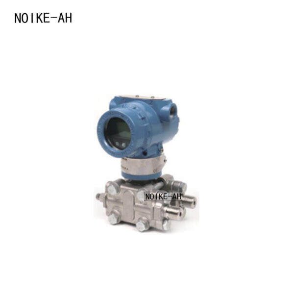
11. NOIKE-AH Smart Pressure Transmitter Solutions
NOIKE-AH provides industrial pressure measurement solutions designed for automation and process control applications.
The product range includes:
- Standard 4-20mA pressure transmitters;
- HART intelligent pressure transmitters;
- RS485 Modbus pressure transmitters;
- Differential pressure transmitters;
- Flush diaphragm pressure transmitters.
Key features:
- High accuracy sensing technology;
- Stable 4-20mA output;
- Multiple communication options;
- Industrial-grade protection;
- Suitable for harsh environments.
NOIKE-AH pressure transmitters are widely applied in:
- Water treatment;
- HVAC systems;
- Industrial automation;
- Chemical processing;
- Energy management.
Conclusion: Understanding Pressure Transmitter Wiring Ensures Reliable Measurement
Correct wiring is the foundation of reliable pressure measurement.
Whether using a traditional 4-20mA pressure transmitter, a HART smart transmitter, or a Modbus RS485 digital pressure transmitter, engineers must understand:
- Wiring principles;
- Power requirements;
- Communication methods;
- Troubleshooting procedures.
For most industrial applications:
- 4-20mA remains the simplest and most reliable solution;
- HART provides advanced configuration while keeping analog compatibility;
- Modbus enables digital networking and smart automation.
Choosing the correct wiring method and transmitter type ensures accurate pressure monitoring, reduces downtime, and improves overall system performance.



