
In pump systems, hydraulic units, air compressors, diaphragm pumps, reciprocating pumps, water treatment skids, and industrial control panels, pressure instrument failure is often caused by selecting only according to normal working pressure.
The real danger is the peak pressure.
A system may normally operate at 8 bar, but pressure peaks during pump start, valve closing, water hammer, hydraulic valve switching, or pump pulsation may be much higher. If this peak pressure exceeds the instrument range or overpressure rating, pressure gauges, pressure transmitters, and pressure switches may fail quickly.
WIKA lists pressure spikes, overpressure, pulsation, and vibration as common causes of pressure gauge failure. Setra also explains that pressure above a transmitter’s overpressure rating but below burst pressure can permanently deform the diaphragm and cause output shift.
Why Normal Pressure Is Not Enough for Selection
Normal working pressure is only the stable operating value.
It does not show what happens during short transient events.
Common pressure peak sources include:
- pump start and stop;
- fast valve closing;
- water hammer;
- check valve slam;
- hydraulic valve switching;
- cylinder end impact;
- diaphragm pump pulsation;
- reciprocating pump pulsation;
- air compressor loading and unloading.
A pressure gauge or transmitter may appear suitable when only normal pressure is considered, but fail when exposed to short pressure peaks.
Typical Symptoms
| Symptom | Likely Cause |
|---|---|
| Gauge pointer does not return to zero | overpressure or pressure spike |
| Gauge pointer bends or hits full scale | transient peak pressure |
| Transmitter zero drift | diaphragm deformation |
| 4–20 mA signal shift | overpressure damage |
| Pressure switch false trip | pressure peak or pulsation |
| New instrument fails again quickly | site pressure spike not corrected |
| Same point repeatedly damages instruments | application condition problem |
WIKA notes that pressure above the overpressure limit is a leading cause of pressure gauge failure, even if the event is short.
Field Troubleshooting Procedure
The correct troubleshooting sequence is:
- Check the failure pattern.
- Confirm the installation point.
- Record normal working pressure.
- Confirm maximum continuous pressure.
- Estimate or measure peak pressure.
- Check pump start, valve closing, water hammer, and hydraulic shock.
- Check whether a snubber or pulsation dampener is installed.
- Confirm gauge range and transmitter overpressure rating.
- Verify the PLC or VFD signal.
- Select the correct protection method.
A snubber can help suppress pressure pulses and pressure peaks before they damage the pressure instrument.
Correct Selection Logic
Do not select only by normal working pressure.
Check:
| Parameter | Purpose |
|---|---|
| Normal working pressure | basic measuring range |
| Maximum continuous pressure | long-term safety |
| Peak pressure | overpressure protection |
| Start-up surge | pump system protection |
| Valve closing speed | water hammer risk |
| Hydraulic shock | transmitter and gauge protection |
| Pulsation | snubber or dampener selection |
| Instrument location | local pressure spike risk |
| Overpressure rating | transmitter survival |
| Control signal | PLC or VFD compatibility |
Recommended Solutions
| Condition | Recommended Solution |
|---|---|
| Stable pressure | standard pressure gauge |
| Pump outlet pressure peaks | liquid-filled gauge plus snubber |
| Strong pulsation | pulsation dampener plus snubber |
| Hydraulic shock | hydraulic snubber plus high overpressure transmitter |
| Water hammer | valve timing, ramp adjustment, and damping |
| Frequent gauge failure | check peak pressure before replacing |
| Transmitter drift | select higher overpressure rating |
| Pressure switch false trip | adjust hysteresis and add damping |
NOIKE-AH Application
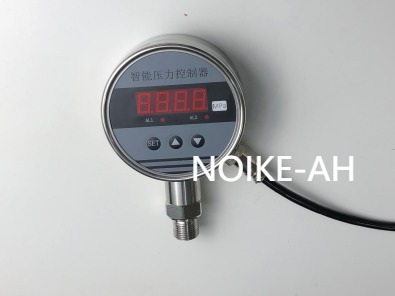
For pump control panels, constant pressure water supply, hydraulic units, air compressors, chemical dosing skids, water treatment systems, and maintenance replacement projects, NOIKE-AH can provide pressure gauges, pressure transmitters, pressure switches, digital pressure gauges, flow switches, flow meters, and level sensors.
Typical configurations include:
| Application | NOIKE-AH Solution |
|---|---|
| Pump outlet pressure peak | liquid-filled pressure gauge, pressure transmitter, pressure switch, snubber |
| High-pressure hydraulic system | high-pressure gauge, high overpressure transmitter, hydraulic snubber |
| Diaphragm pump | pulsation dampener, diaphragm gauge, pressure transmitter |
| Air compressor | pressure gauge, pressure switch, pressure transmitter |
| Maintenance replacement | confirm failure mode before replacing the same model |
Conclusion
Pressure peaks may be much higher than normal working pressure.
Selecting pressure instruments only by working pressure can lead to repeated failure.
The correct solution is not simply choosing a larger range.
A reliable system should include:
proper range + sufficient overpressure rating + snubber or dampener + correct installation point + pressure switch protection + continuous transmitter feedback + local gauge verification.



