
Industrial Pressure Sensor
In industrial automation—whether you are managing pump control panels, VFD constant pressure systems, hydraulic units, or water treatment plants—a “faulty” reading does not always mean a faulty sensor. Replacing the transmitter prematurely is a common, costly mistake. To resolve issues efficiently, you must approach the problem as a signal chain breakdown rather than a single-point failure.
The Signal Chain Model
To locate the fault, visualize your system as a sequential chain:
Actual Pressure → Transmitter → 4–20mA Loop → Wiring → PLC Analog Input (AI) → Raw Data → Scaling/Logic → HMI / PID
1. Fault Layer Analysis
Understanding where the error originates is the first step in effective maintenance.
| Fault Layer | Typical Cause | Diagnostic Symptom |
| Sensor | Drift, physical damage, wrong range | Output (mA) does not match actual pressure |
| Wiring / Loop | No 24VDC, open loop, polarity error, loose terminal | 0mA signal, intermittent loss, or unstable jumping |
| PLC AI | Incorrect input mode, damaged channel, wrong range | Correct mA at terminals, but static/erroneous raw value |
| Scaling | Wrong 4/20mA range mapping, unit conversion error | Correct raw value, but incorrect pressure on HMI |
2. Step-by-Step Troubleshooting Procedure
Step 1: Verify Actual Pressure
Never trust the HMI blindly. Use a local mechanical or digital pressure gauge to verify if the physical pressure matches the process expectation. If the gauge reads correctly but the signal does not, you have confirmed the issue lies within the instrumentation.
Step 2: Measure the 4–20mA Loop
Use a multimeter to measure the current in series with the loop.
- 0mA: Open circuit, broken wire, or loss of loop power.
- 4mA: Valid lower range value (Zero pressure).
- 12mA: Mid-span (50% pressure).
- 20mA: Upper range limit.
- <3.6mA or >21mA: Indicates a hardware fault or loop diagnostic error.
Step 3: Inspect Wiring and Loop Power
Check for environmental factors and installation integrity:
- Power: Confirm 24VDC at the transmitter.
- Configuration: Verify if the device is 2-wire, 3-wire, or 4-wire, and ensure the sourcing/sinking logic matches your PLC input card.
- Integrity: Check for loose terminals, cable damage, and proper shield grounding to prevent EMI.
Step 4: Validate PLC Analog Input (AI)
If the mA signal is perfect, the problem is likely the PLC. Use a loop calibrator to inject a simulated 4mA, 12mA, and 20mA signal directly into the PLC input channel.
- If the Raw Value updates: The PLC is healthy; the issue is the transmitter or field wiring.
- If the Raw Value stays static: The AI channel is misconfigured or damaged.
Step 5: Check Scaling and Software
If the PLC raw value is correct but the HMI display is wrong, the error is in the software:
- Verify Engineering Units: (e.g., bar, MPa, psi).
- Check Tag Mapping: Ensure the register address is correct.
- Verify Range Settings: Does the software range (e.g., 0–10 bar) match the transmitter physical range?
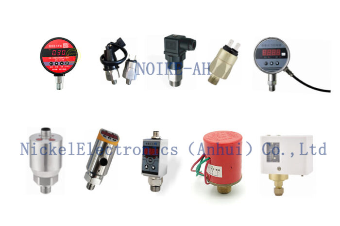
Building a Robust System with NOIKE-AH
For critical infrastructure like cooling water systems or hydraulic units, reliability is built through redundant verification. NOIKE-AH provides a suite of integrated instrumentation designed for high-availability diagnostics:
- Continuous Feedback: High-precision 4–20mA pressure transmitters.
- Local Verification: Pairing transmitters with NOIKE-AH digital pressure gauges for at-a-glance confirmation.
- Safety Interlocks: Utilizing intelligent pressure switches for secondary, independent protection.
- Noise Immunity: Using shielded cabling and signal isolators, especially in environments with high VFD interference.
Conclusion
Don’t reach for the wrench first; reach for the multimeter. By testing the signal chain—from the physical pressure source through to the HMI software—you can isolate the specific layer of failure. Following this diagnostic sequence saves time, reduces unnecessary replacement costs, and ensures the long-term stability of your industrial control system.
Are you currently dealing with an unstable pressure reading in your system, or are you looking to upgrade your instrumentation for better diagnostic visibility?



