
Pressure Sensing
In variable frequency drive (VFD) constant pressure water supply and secondary water supply systems, the stability of the PID closed-loop control relies entirely on the quality of the feedback signal. In many field applications, severe pressure feedback fluctuations and VFD frequency hunting/instability occur. The root cause is frequently not poorly tuned PID parameters, but rather the improper installation of the pressure transmitter too close to the pump discharge outlet, check valves, elbows, or reducers, causing the instrument to capture localized hydraulic noise instead of the stable system pressure.
I. Mechanics of Pump Discharge Pressure Instability
According to fluid dynamics and centrifugal pump research (such as MDPI studies on pump-valve flow fields), rotor-stator interaction (RSI) between the high-speed rotating impeller and the stationary pump casing generates high-frequency pressure pulsations near the discharge outlet. The flow regime in this area is highly complex and characterized by:
- High-Frequency Pressure Pulsations: Periodic hydraulic shocks generated directly by the impeller blades cutting through the fluid.
- Non-Uniform Velocity Distribution: Highly turbulent fluid just exiting the pump discharge where dynamic and static pressures are rapidly converting.
- Localized Turbulence and Eddies: Severe turbulence exacerbated by elbows, tees, reducers, and control valves installed too close to the pump outlet.
- Mechanical and Hydraulic Shocks: Micro-chatter of check valve discs and fluctuations caused by micro-air pockets trapped in the piping.
- Cavitation: The collapse of vapor bubbles as they travel from local low-pressure zones to the high-pressure discharge area, inducing localized water hammer.
Key Takeaway: If a pressure sensor is installed within these turbulent zones, it reads “hydraulic noise.” The VFD PID controller interprets this noise as actual system pressure changes, forcing the drive to constantly adjust its output frequency, which triggers system hunting, oscillation, or resonant instability.
II. Typical Field Symptoms
When a water supply system suffers from an improperly located pressure collection point, it typically exhibits the following symptoms:
- HMI/SCADA Trends: The pressure curve displays erratic, high-frequency sawtooth or sinusoidal fluctuations.
- VFD Operating Status: The output frequency (Hz) constantly hunts up and down, keeping the motor speed in a perpetual state of correction.
- Mechanical Instrumentation: The needle of a standard mechanical pressure gauge near the pump outlet shakes violently, often leading to premature gauge failure.
- Nuisance Alarms: Random low-pressure or high-pressure alarms trip without actual network pressure drops or spikes.
- Ineffective Standard Troubleshooting: Replacing the pressure transmitter with a brand-new unit does not resolve the issue. Increasing the PID integral time ($T_i$) or decreasing the proportional gain ($K_p$) only makes the system sluggish without eliminating the oscillation.
- Aggravated Low-Flow Conditions: Fluctuations worsen significantly during low-demand periods or during multi-pump staging/rotation cycles.
III. Standard Field Troubleshooting & Diagnostic Procedure
Before swapping hardware or modifying control code, field engineers should follow this structured diagnostic sequence:
[Inspect Physical Location] ➔ [Compare Gauge vs. Header Pressure] ➔ [Manual Fixed-Frequency Test] ➔ [Bleed Air & Install Dampeners] ➔ [Relocate to Header] ➔ [Retune PID]
- Step 1: Verify Physical Installation. Check the exact distance between the transmitter and the pump outlet, check valves, elbows, or reducers.
- Step 2: Compare Branch vs. Header Pressure. Monitor the difference in fluctuation amplitudes between the pump branch gauge and the main common discharge header.
- Step 3: Perform Fixed-Frequency Test. Switch the VFD to Manual Mode and lock the output at a fixed frequency (e.g., 40 Hz). If the pressure feedback continues to fluctuate rapidly, the issue is purely physical hydraulic pulsation, not PID loop tuning.
- Step 4: Inspect the Impulse Piping. Check for air pockets, clogging, or welding burrs inside the pressure tapping tube.
- Step 5: Apply Physical Mitigation. If piping relocation is temporarily impossible, install pressure snubbers or pulsation dampeners upstream of the transmitter to absorb hydraulic spikes.
- Step 6: Relocate the Control Point (Root Cause Fix). Migrate the main PID feedback transmitter to a stable section of the common discharge header.
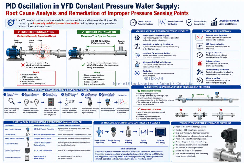
IV. Engineering Specifications for Correct Sensing Point Selection
To ensure stable operation of VFD constant pressure water supply, cooling water loops, and booster systems, the pressure feedback point must meet the following piping guidelines:
✅ Preferred Locations
- The Common Discharge Header: Downstream of the confluence point where multiple pump branches tie in and flow stabilizes.
- Fully Developed Straight Pipe Sections: A straight run of pipe at least 5 to 10 pipe diameters (D) downstream of any valves, pump outlets, elbows, or components that cause flow disturbance.
- Representative Network Points: A location that accurately reflects the static head of the main distribution network.
- Proper Tapping Orientation: Tapped into the side of horizontal piping (avoiding the top where air pockets gather, and the bottom where sediment accumulates).
❌ Prohibited Locations
- Directly upstream or immediately downstream of the pump check valve.
- Inside or adjacent to concentric/eccentric reducers.
- The intersection or cross-center point of piping tees.
V. System-Wide Instrumentation Configuration (Example: NOIKE-AH)
For industrial pump skids, booster systems, HVAC circulation, and reverse osmosis (RO) water treatment systems, robust hardware selection and signal integrity are vital. The following matrix illustrates a typical control loop configuration utilizing the NOIKE-AH instrumentation suite:
| Control Loop Component | Recommended Product Configuration | Function & Technical Features |
| Main Pressure Feedback | NOIKE-AH Pressure Transmitter | Provides a highly accurate 4–20 mA analog feedback signal to the VFD or PLC with excellent noise immunity. |
| Local Indication | NOIKE-AH Digital Pressure Gauge | Provides on-site visual monitoring to compare physical readings against control system values. |
| Safety Interlock & Protection | Intelligent Pressure Switch | Operates independently of the PID loop to provide hardware-level overpressure or dry-run protection. |
| Pulsation Reduction | Stainless Steel Snubber / Damping Device | Installed upstream of instruments to throttle fluid spikes and absorb high-frequency hydraulic noise. |
| Control Logic Execution | PLC Analog Input (AI) / VFD Internal PID | Receives the 4–20 mA loop signal and executes closed-loop PID control algorithms. |
| Electrical Noise Mitigation | Shielded Cable + Signal Isolator | Blocks high-frequency electromagnetic interference (EMI) inside VFD enclosures from disrupting weak analog signals. |
VI. Conclusion: The Logical Chain of Constant Pressure Stability
When troubleshooting VFD PID oscillation and unstable feedback, engineering teams must prioritize a hardware-first, physical-layer-first approach.
$$Stable\,System\,Hydraulics \rightarrow Proper\,Sensing\,Point \rightarrow Physical\,Damping \rightarrow Signal\,Filtering \rightarrow Software\,PID\,Tuning$$
Core Conclusion: Stable fluid dynamics are the absolute foundation of reliable VFD PID control. If a pressure transmitter is allowed to capture localized turbulent pulsations, software-level filtering and PID parameter adjustments will only act as temporary band-aids. Rectifying the physical sensing location is the golden rule for resolving constant pressure system oscillations permanently.



