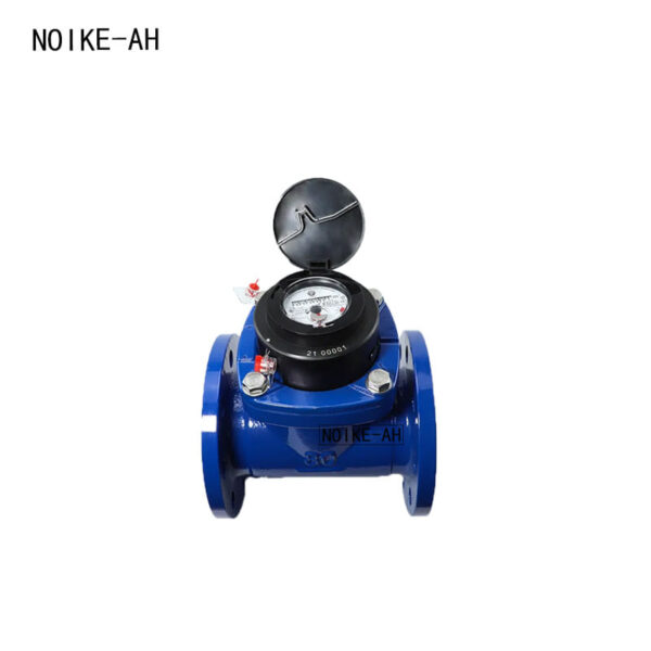
Turbine Flow Meter NK-GF-110 series | Precision Liquid Flow Sensor for Water, Diesel & Fuel | NOIKE-AH
- Brand: NOIKE-AH
- Model: NK-GF-110 series
Specification
Product Overview
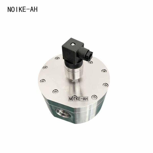
The NOIKE-AH Turbine Flow Meter NK-GF-110 is a precision flow measurement instrument that measures liquid flow using the rotational speed of a turbine impeller.
When fluid passes through the sensor, the impeller rotates under the force of the flowing medium. The rotational speed of the impeller is proportional to the average flow velocity in the pipeline. The rotating impeller periodically changes the magnetic reluctance of the magneto-electric converter, causing periodic changes in the magnetic flux inside the detection coil. These changes generate electrical pulse signals, which are amplified and transmitted to a display instrument for flow indication and measurement.
The sensor is available in multiple versions, including standard, high-precision, and wear-resistant (hard alloy) models. Universal amplifiers are available, and the sensor can be supplied in standard or explosion-proof versions. It can also be used together with a flow totalizer for accumulated flow measurement.
Why Choose the NOIKE-AH Turbine Flow Meter NK-GF-110?
The Turbine Flow Meter NK-GF-110 is designed for accurate liquid flow measurement in industrial applications where reliable performance and flexible output options are required.
Key Advantages
- High measurement accuracy
- Suitable for various liquid media
- Multiple sensor configurations available
- Wear-resistant hard alloy option
- Corrosion-resistant versions available
- Multiple output signal options
- Supports instantaneous and total flow measurement
- Compatible with industrial monitoring and control systems
Working Principle
The Turbine Flow Meter NK-GF-110 measures liquid flow by detecting the rotational speed of a turbine impeller installed inside the flow path.
As the liquid flows through the sensor, the impeller rotates at a speed proportional to the flow velocity. The rotating impeller periodically changes the magnetic resistance within the magnetic pickup, generating electrical pulse signals. These pulse signals are processed by an amplifier and transmitted to the display or control system for flow rate and total flow calculation.
Typical Applications
The Turbine Flow Meter NK-GF-110 is suitable for measuring the flow of liquids such as:
- Water
- Diesel
- Gasoline
Typical industries include:
- Petroleum
- Chemical processing
- Metallurgy
- Scientific research
- Industrial process control
- Flow monitoring systems
Key Features
- Precision turbine flow measurement
- High measurement accuracy
- Standard, high-precision, and wear-resistant models available
- Wear-resistant hard alloy shaft and bearing options
- Corrosion-resistant versions for compatible media
- Multiple customized sensor options
- Pulse output
- Optional 4–20 mA output
- Instantaneous and accumulated flow display support
Parameters
|
NK110
|
0.25
|
A
|
2
|
B
|
P1
|
DC
|
/Z
|
Description
|
|
NK110
|
NK110 Turbine Flowmeter
|
|||||||
|
Nominal Diameter
|
0.25
|
DN4, DN6, DN10, DN15, DN20, DN25, DN32, DN40, DN50, DN65, DN80, DN100, DN125, DN150, DN200, DN250, DN300
|
||||||
|
Output Signal
|
B
|
No output (field display only)
|
||||||
|
N
|
Pulse output
|
|||||||
|
C
|
Analog 4~20mA (with field display and signal output)
|
|||||||
|
C1
|
Analog 0~5V/0~10V signal
|
|||||||
|
C2
|
Field display with HART protocol
|
|||||||
|
A
|
Transmitter, two-wire system 4~20mA output
|
|||||||
|
Connection Type
|
1
|
Threaded sealed connection
|
||||||
|
2
|
Flanged connection
|
|||||||
|
3
|
Sanitary clamp connection
|
|||||||
|
4
|
Quick-insert clamp connection
|
|||||||
|
Accuracy
|
A
|
Accuracy ±0.2%R (for DN15 and above)
|
||||||
|
B
|
Accuracy ±0.5%R (for DN10 and above)
|
|||||||
|
C
|
Accuracy ±1.0%R
|
|||||||
|
Pressure Rating
|
P1
|
Pressure resistance: 16bar
|
||||||
|
P2
|
Pressure resistance: 25bar
|
|||||||
|
P3
|
Pressure resistance: 40bar
|
|||||||
|
P4
|
Pressure resistance: 63bar
|
|||||||
|
P5
|
Pressure resistance: 100bar (for DN≤50)
|
|||||||
|
P6
|
Pressure resistance: 250bar (for DN≤50)
|
|||||||
|
P7
|
Pressure resistance: 400bar (for DN≤50)
|
|||||||
|
Power Supply Mode
|
DC
|
Power supply: DC 5~24V
|
||||||
|
B
|
Power supply: 3.6V lithium battery (pulse signal output only)
|
|||||||
|
Optional Items
|
/HT
|
High-temperature version
|
||||||
|
/HZ
|
Special customized version
|
|||||||
|
/HK
|
Wireless transmission function
|
|||||||
|
/HC
|
Special customized flow range (range to be specified)
|
Selection Table
|
NK110
|
0.25
|
A
|
2
|
B
|
P1
|
DC
|
/Z
|
Description
|
|
NK110
|
NK110 Turbine Flowmeter
|
|||||||
|
Nominal Diameter
|
0.25
|
DN4, DN6, DN10, DN15, DN20, DN25, DN32, DN40, DN50, DN65, DN80, DN100, DN125, DN150, DN200, DN250, DN300
|
||||||
|
Output Signal
|
B
|
No output (field display only)
|
||||||
|
N
|
Pulse output
|
|||||||
|
C
|
Analog 4~20mA (field display with signal)
|
|||||||
|
C1
|
Analog 05V/010V signal
|
|||||||
|
C2
|
Field display with HART protocol
|
|||||||
|
A
|
Transmitter, output two-wire 4~20mA
|
|||||||
|
Connection Type
|
1
|
Threaded sealed connection
|
||||||
|
2
|
Flanged connection
|
|||||||
|
3
|
Hygienic clamp connection
|
|||||||
|
4
|
Quick insert clamp connection
|
|||||||
|
Accuracy
|
A
|
Accuracy ±0.2%R (for DN15 and above)
|
||||||
|
B
|
Accuracy ±0.5%R (for DN10 and above)
|
|||||||
|
C
|
Accuracy ±1.0%R
|
|||||||
|
Pressure Rating
|
P1
|
Pressure resistance: 16bar
|
||||||
|
P2
|
Pressure resistance: 25bar
|
|||||||
|
P3
|
Pressure resistance: 40bar
|
|||||||
|
P4
|
Pressure resistance: 63bar
|
|||||||
|
P5
|
Pressure resistance: 100bar (for DN≤50)
|
|||||||
|
P6
|
Pressure resistance: 250bar (for DN≤50)
|
|||||||
|
P7
|
Pressure resistance: 400bar (for DN≤50)
|
|||||||
|
Power Supply Mode
|
DC
|
Power supply: DC 5~24V
|
||||||
|
B
|
Power supply: 3.6V lithium battery (only for pulse signal output)
|
|||||||
|
Optional Items
|
/HT
|
High temperature version
|
||||||
|
/HZ
|
Special customized version
|
|||||||
|
/HK
|
Wireless transmission function
|
|||||||
|
/HC
|
Special customized flow range (need to specify range)
|
Technical Specifications
| Parameter | Specification |
|---|---|
| Measuring Principle | Turbine Flow Measurement |
| Measuring Media | Water, diesel, gasoline and other compatible liquids |
| Accuracy | ±1% R, ±0.5% R, High-precision model: ±0.2% R |
| Sensor Types | Standard, High-precision, Wear-resistant |
| Wear-resistant Version | Hard alloy shaft and bearings |
| Corrosion-resistant Version | Suitable for compatible corrosive media such as seawater, oxygenated water and acetic acid |
| Customized Versions | Low-temperature type, Bidirectional type, Downhole type, Sand-mixing type and other customized sensors |
| Output Signal | Pulse output |
| Optional Output | 4–20 mA DC |
| Display | Instantaneous flow and accumulated flow (when used with compatible display instruments) |
Typical Application Example
In industrial liquid transfer systems, turbine flow sensors are commonly installed to monitor the flow rate of liquids such as water, diesel, or gasoline. When connected to a compatible flow totalizer or control system, the sensor provides both instantaneous flow data and accumulated flow information, helping operators monitor process conditions and perform flow management in industrial applications.
Frequently Asked Questions (FAQ)
What media can the Turbine Flow Meter NK-GF-110 measure?
The sensor is suitable for measuring compatible liquids such as:
- Water
- Diesel
- Gasoline
What accuracy levels are available?
Standard models provide ±1% R or ±0.5% R accuracy, while high-precision models can achieve ±0.2% R.
Are wear-resistant models available?
Yes. Wear-resistant models use hard alloy shafts and bearings and are suitable for media containing impurities such as sand particles.
Are corrosion-resistant versions available?
Yes. Corrosion-resistant versions are suitable for compatible media including seawater, oxygenated water, and acetic acid.
What output signals are supported?
Available outputs include:
- Pulse output
- Optional 4–20 mA DC output
Can the sensor display accumulated flow?
Yes. When used with a compatible flow totalizer or display instrument, the system can display both instantaneous flow and accumulated flow.
Installation Notes
- Select the appropriate sensor type according to the measured liquid and operating conditions.
- Match the sensor with a compatible display instrument or flow totalizer when accumulated flow measurement is required.
- Choose wear-resistant or corrosion-resistant models according to the application environment and medium characteristics.
Table of Contents
Talk With Us
- [email protected]
- +86 180 5512 0225
- +86(0551)-65501008
- Address: 206, Block B, No. 2 Tianda Road, High-tech Zone, Hefei City, Anhui Province, China
- We will respond to you within five minutes.