
Pressure Transmitter, Pressure Switch, and Mechanical Pressure Gauge
In pump systems, constant pressure water supply, hydraulic units, air compressors, water treatment systems, filtration skids, and industrial control panels, pressure transmitters, pressure switches, and mechanical pressure gauges should not always be installed at the same point.
Each instrument has a different function.
| Instrument | Main Function | Installation Logic |
|---|---|---|
| Pressure transmitter | continuous pressure measurement and control feedback | install where the pressure represents the control target |
| Pressure switch | alarm, protection, interlock, start and stop control | install where the dangerous pressure condition must be detected |
| Mechanical pressure gauge | local indication, inspection, commissioning, verification | install where operators can read and maintain it safely |
Pressure Transmitter Location
A pressure transmitter should be installed at a stable pressure point that represents the system pressure required for control or monitoring.
Typical locations:
| Application | Recommended Location |
|---|---|
| constant pressure water supply | common discharge header after pumps combine |
| pump suction monitoring | suction header before pump inlet |
| filter clogging trend | filter inlet and outlet, or differential pressure point |
| hydraulic monitoring | main manifold or controlled pressure point |
| compressed air monitoring | air receiver or main air header |
| remote monitoring | representative system pressure point |
For constant pressure pump control, the main pressure transmitter should usually be installed on the common discharge header, not directly near a single pump outlet.
Pressure Switch Location
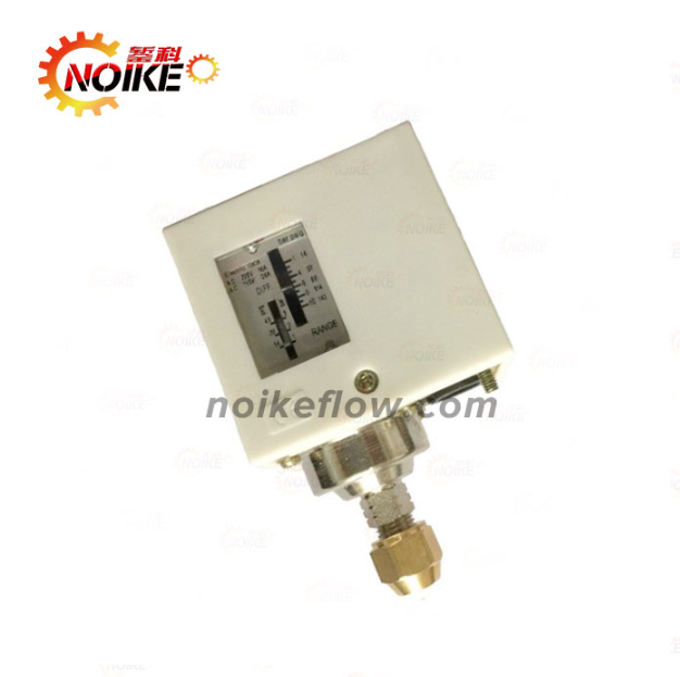
A pressure switch should be installed at the protection point.
Typical examples:
| Function | Recommended Location |
|---|---|
| high pressure protection | discharge header or high-risk pressure point |
| low pressure protection | suction line or supply side |
| dry-run protection | suction line, tank level point, or flow point |
| filter clogging alarm | across filter inlet and outlet |
| hydraulic pressure ready signal | hydraulic manifold or actuator pressure point |
| air compressor control | air receiver or compressor control pressure point |
Low pressure protection should not be installed only on the discharge side if the purpose is dry-run protection.
Mechanical Pressure Gauge Location
A mechanical pressure gauge is used for local reading and maintenance verification.
Typical locations:
| Application | Recommended Location |
|---|---|
| pump system | suction, discharge, and common header |
| hydraulic system | pump outlet, manifold, and test points |
| filtration system | filter inlet and outlet |
| steam system | visible safe location with siphon protection |
| wastewater or slurry | diaphragm gauge or anti-clog structure |
| chemical liquid | diaphragm seal gauge with compatible wetted material |
WIKA notes that vibration, pulsation, pressure spikes, overpressure, corrosion, and clogging are common causes of pressure gauge failure. A gauge should not be installed at a severe vibration or pulsation point without protection. (WIKA blog)
Recommended Layout by System
Constant Pressure Water Supply
| Instrument | Recommended Location |
|---|---|
| pressure transmitter | common discharge header |
| high pressure switch | discharge header |
| low pressure switch | suction side or water supply side |
| mechanical pressure gauge | suction, pump outlet, and discharge header |
| flow switch or level sensor | for dry-run protection assistance |
Hydraulic System
| Instrument | Recommended Location |
|---|---|
| pressure transmitter | manifold or controlled pressure point |
| pressure switch | high pressure trip or pressure ready point |
| pressure gauge | pump outlet, manifold, and test point |
| snubber | before gauge, transmitter, or switch |
| safety gauge | high-pressure operator-accessible location |
Filtration System
| Instrument | Recommended Location |
|---|---|
| pressure gauge | filter inlet and outlet |
| differential pressure switch | across filter inlet and outlet |
| differential pressure transmitter | across filter inlet and outlet |
| pressure transmitter | inlet and outlet if pressure trend is required |
A filter should not be judged only by one pressure point. Differential pressure is the key indicator for clogging.
NOIKE-AH Application
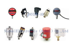
For pump control panels, constant pressure water supply, hydraulic units, air compressors, filtration skids, chemical dosing systems, and water treatment systems, NOIKE-AH can provide pressure transmitters, pressure switches, mechanical pressure gauges, digital pressure gauges, flow switches, flow meters, and level sensors.
Typical configurations:
| Application | NOIKE-AH Solution |
|---|---|
| constant pressure pump system | pressure transmitter on common discharge header, pressure switch for protection, pressure gauge for local verification |
| hydraulic unit | high pressure transmitter, intelligent pressure switch, liquid-filled pressure gauge, hydraulic snubber |
| filter skid | inlet and outlet gauges, differential pressure switch or transmitter |
| chemical dosing system | diaphragm seal gauge, diaphragm seal transmitter, pressure switch, pulsation dampener |
| dry-run protection | suction pressure switch, flow switch, and level sensor combination |
Conclusion
The correct installation position depends on instrument function.
Use:
- pressure transmitter for continuous feedback and control;
- pressure switch for alarm, protection, and interlock;
- mechanical pressure gauge for local indication and maintenance verification.
The correct layout is not simply installing all instruments at one convenient tapping point.
A reliable system should include:
control feedback point + safety protection point + local verification point
The correct selection sequence is:
system purpose → instrument function → measuring point → pulsation and pressure spike risk → medium risk → protection accessories → control panel signal → maintenance access.



