
High Hydraulic Pressure
In heavy-duty industrial environments—such as hydraulic power units (HPUs), hydraulic presses, injection molding machines, mobile hydraulics, lubrication systems, and hydraulic control panels—selecting a pressure gauge or transmitter based solely on nominal working pressure is a recipe for rapid equipment failure.
Hydraulic systems are notoriously harsh on instrumentation. They subject devices to high working pressures, sudden pressure spikes, hydraulic shock (fluid hammer), pump pulsation, valve switching impacts, mechanical vibration, and extreme oil temperature variations.
According to industry authority WIKA, pressure spikes, overpressure, pulsation, and vibration are the leading catalysts for premature pressure gauge failure. To counter these forces, AMETEK emphasizes that installing snubbers and overpressure protectors is essential to shield gauges and transducers from catastrophic pressure surges and destructive system pulsations.
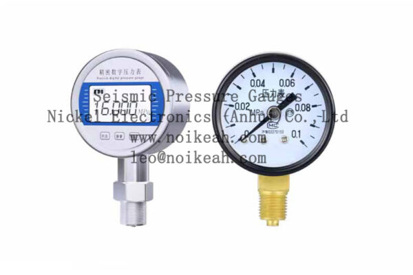
Why Hydraulic Pressure Instruments Fail
The primary reason for instrumentation failure is that the transient peak pressure within a hydraulic loop is often exponentially higher than the steady-state operating pressure displayed on a control room HMI or standard gauge.
Common Sources of Destructive Transient Pressure:
- Rapid solenoid valve switching and directional control changes
- Hydraulic cylinder end-of-stroke impact
- Sudden, severe mechanical load variations
- Safety relief valve response delays
- High-frequency pump pressure ripples or flow pulsations
- Rigid, unyielding piping networks that cannot absorb shock
- Entrained air within the hydraulic fluid, causing localized implosions
- Bladder or gas pre-charge failure in hydraulic accumulators
Technical Insight: For electronic pressure transmitters, experiencing pressures above the manufacturer’s specified overpressure rating can permanently deform the internal sensing diaphragm. This causes an irreversible zero-point shift or drift in output, even if the pressure never reaches the catastrophic burst pressure limit.
Deciphering Failure Symptoms in the Field
When a hydraulic pressure instrument fails, its physical or electrical state provides critical diagnostic clues regarding the root cause:
| Observed Symptom | Likely Root Cause | Field Implication |
| Gauge pointer does not return to zero | Overpressure event or permanent Bourdon tube deformation | Mechanical calibration lost permanently |
| Pointer is visibly bent, broken, or loose | Severe, sudden hydraulic shock or pressure spike | High-velocity mechanical impact inside case |
| Transmitter experiences zero shift | Sensing diaphragm deformation | Calibrated base-line is ruined |
| 4–20mA output drifts over time | Sustained overpressure damage or fatigue | Data integrity compromised in control loop |
| Pressure switch contacts flicker/chatter | Excessive pump pulsation or insufficient hysteresis | Electrical noise, premature relay failure |
| New instrument fails rapidly after replacement | Unmitigated, ongoing hydraulic shock loop | Systemic design flaw, not a bad instrument |
| HMI software and local gauge disagree | Local gauge damage, transmitter drift, or PLC scaling | Signal chain mismatch |
As highlighted by Swagelok, a bent or damaged gauge pointer is a classic indicator of a sudden pressure spike, typically triggered by rapid pump cycling or valve operations. Left unaddressed, these spikes lead to Bourdon tube rupture and total gauge failure.
The Correct Selection Logic for Hydraulic Systems
To prevent premature instrument failure, engineers must move away from nominal-pressure-based selection. When designing or retrofitting a hydraulic system, analyze the following matrix before specifying an instrument:
$$\text{Normal Operating Pressure} \longrightarrow \text{Relief Valve Crack Pressure} \longrightarrow \text{Peak Dynamic Spikes} \longrightarrow \text{Overpressure/Burst Ratings}$$
Key Engineering Checklists:
- The Dynamic Environment: Map out the maximum working pressure, the maximum relief valve setting, and estimated peak transient pressures.
- The Pulse Profile: Evaluate the frequency of the pressure ripple and valve switching shocks.
- The Safety Margins: Ensure the instrument’s overpressure rating exceeds the highest possible system spike, and verify the burst pressure safety factor.
- The Protective Hardware: Determine if the application requires inline snubbers, internal damping mechanisms, or specialized PLC/HMI signal filtering.
Proven Application-Specific Solutions
Different hydraulic challenges require distinct hardware solutions. DwyerOmega notes that pressure snubbers are explicitly designed to protect sensitive pressure transducers, gauges, and switches from the destructive energy of pressure spikes, surges, and water hammer.
| Hydraulic Application / Challenge | Recommended Engineering Solution |
| Local High-Pressure Indication | Liquid-filled (glycerin/silicone) high-pressure gauge |
| Severe Hydraulic Shock Line | Inline mechanical porous or piston-style hydraulic snubber |
| Transmitter Longevity & Protection | Pressure transmitter featuring a high overpressure rating ($2\times$ to $4\times$ FS) |
| Continuous PLC Process Monitoring | Premium 4–20mA or 0–10V industrial pressure transmitter |
| Interlock & “Pressure Ready” Signals | Heavy-duty pressure switch with adjustable hysteresis |
| High-Pressure Emergency Trip | Dedicated, independent mechanical pressure switch |
| Unstable Digital Control Signals | Hardware snubber combined with software-based PLC input filtering |
| High Structural/Equipment Vibration | Case-isolated, vibration-resistant dampened gauge |
Heavy-Duty Industrial Applications: NOIKE-AH Portfolio
For critical deployments across hydraulic power units, industrial presses, injection molding machines, mobile yellow-goods, and centralized lubrication systems, NOIKE-AH delivers ruggedized instrumentation engineered to withstand severe transient spikes.
NOIKE-AH Recommended Configuration Framework:
┌────────────────────────────────────────────────────────────────────────┐
│                    NOIKE-AH Hydraulic Protection Layout                │
├──────────────────────────────┬─────────────────────────────────────────┤
│ System Function              │ Specified NOIKE-AH Product Solution     │
├──────────────────────────────┼─────────────────────────────────────────┤
│ Local Visual Indication      │ Liquid-Filled High-Pressure Gauge       │
│ Continuous Digital Control   │ High-Overpressure 4–20mA Transmitter     │
│ Hardware Safety Interlock    │ High-Proof Pressure Switch              │
│ Shock & Surge Suppression    │ Heavy-Duty Hydraulic Snubber / Damper   │
│ Control Room Diagnostics     │ PLC Loop Evaluation (mA vs Raw Value)   │
└──────────────────────────────┴─────────────────────────────────────────┘
Conclusion: The Diagnostic Workflow
Standard pressure gauges and electronic sensors will inevitably fail in high-pressure hydraulic loops if system spikes, transient shocks, and overpressure thresholds are ignored.
When an instrument fails or behaves erratically, avoid guessing. Follow this precise troubleshooting sequence to locate the root cause:
$$\text{Failure Pattern Ident.} \rightarrow \text{Installation Point} \rightarrow \text{Normal Pressure Check} \rightarrow \text{Peak Pressure Capture} \rightarrow \text{Relief Valve Review} \rightarrow \text{Shock Analysis} \rightarrow \text{Snubber Inspection} \rightarrow \text{Gauge Range/Transmitter Rating Verification} \rightarrow \text{PLC Signal Check}$$
A truly reliable, resilient hydraulic pressure measurement solution requires a multi-layered approach:
$$\text{Proper Scale Range} + \text{High Overpressure Capability} + \text{Mechanical Hydraulic Snubber} + \text{Optimized Tapping Point} + \text{Independent Safety Switches} + \text{PLC Diagnostics}$$



