
Flow Meter
Accurate fluid measurement is the cornerstone of modern industrial process automation, chemical processing, and municipal water management. Choosing the correct instrumentation, however, presents a multi-variable optimization challenge. Missteps during the selection phase do not merely result in minor measurement inaccuracies; they cause catastrophic system downtime, premature component wear, and bloated capital expenditure.
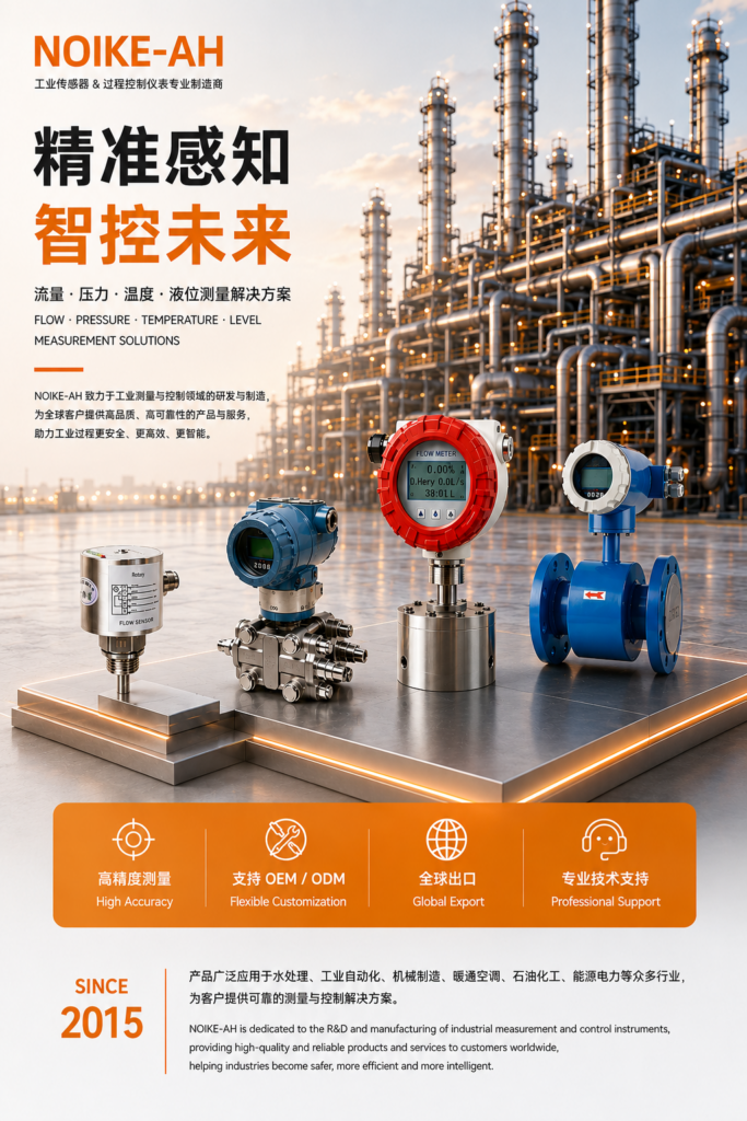
As a leading manufacturer of precision industrial sensors, NOIKE-AH (臬克) frequently analyzes system diagnostics where flow sensors fail prematurely. In this comprehensive technical guide, we dissect the top 5 mistakes engineers make during the industrial flow meter selection process and provide robust, field-tested engineering solutions.
1. Ignoring Fluid Viscosity and Flow Profiles
A frequent error is assuming that a meter designed for water will perform identically when measuring high-viscosity fluids like lubricants, heavy oils, resins, or liquid polymers. Fluid viscosity directly influences the Reynolds number (Re), which defines whether the fluid flow profile within the pipe is laminar, transitional, or turbulent.
The Reynolds number is calculated via the formula:
Re = (ρ × v × D) / μ
Where ρ is fluid density, v is flow velocity, D is internal pipe diameter, and μ is dynamic viscosity. High-viscosity fluids yield low Reynolds numbers, causing a laminar velocity profile where fluid moves fastest in the center and slowest at the pipe wall. Velocity-based flow meters (such as standard turbine or ultrasonic meters) often suffer severe non-linear errors under these conditions.
Engineering Solution: For high-viscosity media or high-pressure environments, positive displacement mechanisms are required. The NOIKE-AH Oval Gear Flow Transmitter relies on mechanical gear meshing where fluid displacement is directly proportional to rotation. It handles extreme viscosities seamlessly and operates under high-pressure conditions up to 70 MPa, making it ideal for hydraulic benches and fuel monitoring systems.
2. Overlooking Fluid Conductivity (The Electromagnetic Trap)
Electromagnetic flowmeters (Magmeters) are highly favored because they feature an unobstructed flow tube, resulting in zero pressure drop and excellent resistance to clogging. However, their physical principle relies strictly on Faraday’s Law of Electromagnetic Induction:
E = B × v × D
Where E is the induced voltage, B is the magnetic field strength, v is fluid velocity, and D is the distance between electrodes. This phenomenon requires the process fluid to possess a minimum electrical conductivity threshold—typically ≥ 5 μS/cm.
Specifying a magmeter for non-conductive fluids, such as demineralized pure water, hydrocarbons, alcohols, or petroleum-based solvents, will result in complete signal failure. Conversely, failing to select the right liner materials for corrosive conductive slurries will lead to rapid electrode degradation.
Engineering Solution: Verify fluid properties beforehand. For conductive fluids (municipal water, wastewater, chemical slurries), the NOIKE-AH NSC100 Electromagnetic Flowmeter delivers exceptional ±0.5% precision across line sizes from DN15 to DN600, compliant with ISO 4064 and OIML R49 standards. For non-conductive fluids, pivot to positive displacement, thermal, or ultrasonic technologies.
3. Misjudging Flow Profile Disturbances and Straight Pipe Runs
Most velocity-dependent flow meters require a fully developed, symmetrical flow profile to guarantee specified accuracy. Upstream components such as elbows, valves, pumps, and reducers introduce swirl and asymmetric velocity distortions. If a flow meter is installed too close to these disturbances, its readings will drift significantly.
Engineers often fail to allocate sufficient straight pipe runs (typically expressed as multiples of nominal diameter, e.g., 10D upstream and 5D downstream) in tight spatial layouts like skid packages or pure water purification workshops.
Alternative Flow Switching Solutions
When the objective is flow control, system protection, or pump dry-run prevention rather than fiscal metering, forcing long straight runs is impractical. In these scenarios, solid-state thermal dispersion or electronic switches are superior.
- NOIKE-AH NK600 Stainless Steel Thermal Flow Switch: Utilizes thermal diffusion principles with no moving parts, offering high sensitivity to micro-flow fluctuations and maximum resistance to wear.
- NOIKE-AH NK300B Electronic Flow Switch: Provides intelligent digital control and rapid response times within compact footprints.
4. Sizing the Flow Meter Based on Nominal Pipe Size
Sizing a flow meter simply to match the existing process pipe diameter is one of the most pervasive design errors. Piping networks are frequently oversized to minimize pressure drops or accommodate future plant expansions. Operating a flow meter in an oversized pipe means the actual fluid velocity may drop below the meter’s minimum measurable threshold (the cut-off flow rate).
Conversely, if a pipe is undersized and fluid velocities are excessively high, placing a mechanical flow meter in that stream results in severe pressure drops, cavitation, and accelerated mechanical degradation of internal parts.
Engineering Solution: Size the meter according to the minimum, normal, and maximum operational flow rates, checking the meter’s turndown ratio (the ratio of maximum to minimum measurable flow). If the optimum meter size is smaller than the pipe size, use concentric reducers. Ensure that fluid velocity remains within the optimal limits of the sensor technology.
5. Disregarding Harsh Environmental Conditions and Regulatory Certifications
Industrial environments expose sensors to extreme physical stress. Selecting a meter purely based on laboratory performance specifications while ignoring ambient realities will lead to rapid field failure. Key environmental stressors include:
- Explosive Hazards: Environments with combustible gases or dust require strict explosion-proof certifications. Using non-certified meters risks devastating industrial accidents. The NOIKE-AH NK33EX Series Explosion-Proof Flow Switch is fully ATEX-certified, explicitly engineered for volatile, high-risk chemical environments.
- Chemical Incompatibility: Wetted parts must withstand corrosive or abrasive fluids. For instance, wastewater treatment requires robust electrodes, while pure water workshops require sanitary, non-contaminating housings like the NOIKE-AH WP-DJ Electrode Level Switch for liquid control.
Industrial Flow Sensor Selection Matrix
| Technology Type PDF | Target Fluid Type PDF | Key Advantages PDF | Major Constraints PDF | Recommended Model PDF |
| Electromagnetic | Conductive liquids, slurries, wastewater | Zero pressure drop, high accuracy (±0.5%), low maintenance | Requires conductivity ≥ 5 μS/cm; sensitive to orientation | NOIKE-AH NSC100 |
| Positive Displacement (Oval Gear) | High-viscosity oils, lubricants, fuels | Immune to flow profile distortions, handles up to 70 MPa | Mechanical moving parts, potential pressure drop at high flows | NOIKE-AH Gear Series |
| Thermal Dispersion | Gases, clean liquids, micro-flows | No moving parts, highly sensitive to low flow velocities | Slower response times, affected by fluid thermal conductivity alterations | NOIKE-AH NK600 |
| Ultrasonic (Water Meter) | Bulk water, industrial water, low turbidity fluids | Excellent turndown ratio, long-term stability, low maintenance cost | Higher initial capital investment | NOIKE-AH Ultrasonic Series |
The Supply Chain Dimension: Overcoming Rigid Vendor Constraints
In addition to technical selection errors, engineers often face procurement bottlenecks. Global automation conglomerates enforce restrictive Minimum Order Quantities (MOQs), high pricing premiums, and slow technical support response times. This hinders prototyping, custom skid manufacturing, and small-scale system integrations.
To bridge this gap, NOIKE-AH (臬克) offers a highly agile engineering and manufacturing infrastructure:
- Flexible MOQ: Support for flexible small-batch customization (OEM/ODM) starting from 1 piece.
- Rapid Response: Strict 5-minute technical inquiry response protocol to keep engineering design cycles on schedule.
- Global Compliance: CE-certified, rigorously tested instruments ensuring global compatibility at highly competitive cost structures.



