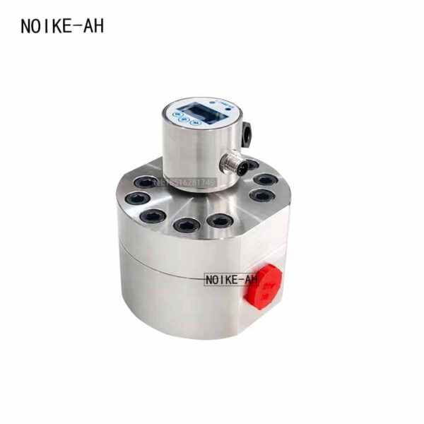
Pulse Output Dual Oval Gear Flow Meter NKGF | High Accuracy Positive Displacement Flow Meter
Brand: NOIKE-AH
Model:NKGF
Specification
Product Overview
The Oval Gear Flow Meter NKGF is a high-precision positive displacement flow meter designed for continuous and intermittent measurement of low-flow and high-viscosity liquids. Using precision-machined oval gears, the meter accurately measures the volume of liquid passing through the measuring chamber, delivering exceptional repeatability and long-term stability.
Unlike turbine or electromagnetic flow meters, the NKGF series maintains excellent accuracy regardless of viscosity changes, making it ideal for oils, resins, adhesives, fuels, lubricants, chemicals, and other difficult-to-measure liquids.
Available with pulse, 4-20mA, PNP/NPN switch outputs, the NKGF series can be integrated into PLC, DCS, SCADA, batching, and process automation systems.
Working Principle
The Gear Flow Meter NKGF series operates using the positive displacement principle.
As liquid enters the measuring chamber, it drives two precision oval gears to rotate. Each complete gear rotation displaces a fixed and known volume of liquid. Electronic sensors detect each gear rotation without physical contact and convert it into pulse signals or analog outputs.
Since every rotation represents an exact volume, the flow meter delivers highly accurate volumetric measurement independent of flow profile or viscosity variation.
This design makes the flow meter NKGF especially suitable for:
- Low-flow measurement
- High-viscosity liquids
- Dosing systems
- Batch control
- Metering applications
Product Features
- High measurement accuracy up to ±0.5% F.S.
- Excellent repeatability of ±0.1% F.S.
- Wide measuring range from 0.005 to 330 L/min
- High pressure resistance up to 400 bar (stainless steel version)
- Suitable for low and high temperature media (-196°C to 200°C)
- Measures high-viscosity liquids up to 10,000 cSt
- Pulse, 4–20mA, PNP and NPN outputs available
- Optional LCD/LED digital display
- Low starting flow rate
- Wide turndown ratio (up to 100:1)
- Corrosion-resistant aluminum, stainless steel, or PP housing
- Compact structure with low vibration and long service life
- Ideal for continuous monitoring or batching systems
Technical Specifications
| Parameter | Specification |
|---|---|
| Measuring Range | 0.005–330 L/min (custom available) |
| Accuracy | ±0.5% F.S. |
| Repeatability | ±0.1% F.S. |
| Output Signal | Pulse, 4–20mA, PNP/NPN |
| Power Supply | 16–30 VDC |
| Pressure Rating | Aluminum: 150 bar; Stainless Steel: 400 bar; PP: 50 bar |
| Measuring Principle | Positive Displacement (Oval Gear) |
| Housing Material | Aluminum, Stainless Steel, PP |
| Display Housing | Stainless Steel |
| Medium Temperature | -196°C to 200°C (depending on configuration) |
| Protection | Optional according to configuration |
Typical Applications
The NKGF series is suitable for accurate flow measurement in numerous industrial processes.
Chemical Industry
- Additives
- Catalysts
- Corrosion inhibitors
- Solvents
- Acids
- Alkalis
- Resins
Petroleum Industry
- Fuel oil
- Diesel
- Heavy oil
- Hydraulic oil
- Lubricating oil
- Gear oil
Food & Beverage
- Edible oil
- Fish oil
- Syrup
- Honey
- Flavoring
- Food filling systems
Pharmaceutical Industry
- Alcohol
- Glycerin
- Medical liquids
- Coating solutions
Paint & Ink
- Printing ink
- Coatings
- Pigments
- Paint circulation systems
Adhesive Industry
- Sealants
- Hot-melt adhesive
- Polyurethane
- Epoxy resin
Environmental Protection
- Water treatment chemicals
- Dosing systems
- Chemical injection
Other Industries
- Automotive manufacturing
- Aerospace
- Mining
- Power generation
- Plastics
- Machinery
- Packaging equipment
Suitable Media
The NKGF gear flow meter is designed for both low and high-viscosity liquids, including:
- Hydraulic oil
- Lubricating oil
- Heavy fuel oil
- Diesel
- Biodiesel
- Grease
- Resin
- Glue
- Polyurethane
- Epoxy
- Paint
- Ink
- Asphalt
- Solvents
- Refrigerants
- Liquid nitrogen
- Food oils
- Syrup
- Honey
- Fish oil
- Chemical additives
Installation Recommendations
For optimal performance:
- Install the meter in a location free from excessive vibration and strong electromagnetic interference.
- Horizontal installation is recommended. If installed vertically, ensure the flow direction is upward.
- Keep the pipeline completely filled with liquid during operation.
- Install a filter upstream to prevent solid particles from entering the measuring chamber.
- Install the control valve downstream of the flow meter.
- Provide a bypass line for convenient maintenance.
- Use shielded signal cables and ground the shielding at one end to reduce electrical interference.
- Ensure the pipeline is clean before commissioning.
Advantages of the Gear Flow Meter NKGF
Compared with turbine and electromagnetic flow meters, the NKGF series offers:
- Higher accuracy for high-viscosity liquids
- Excellent repeatability
- Low starting flow
- Stable measurement under fluctuating flow conditions
- No dependence on fluid conductivity
- Minimal influence from viscosity changes
- Long service life
- Easy integration into industrial automation systems
Why Choose NOIKE-AH Gear Flow Meter NKGF ?
The NOIKE-AH NKGF Series is engineered for demanding industrial applications requiring precise liquid flow measurement. With robust construction, flexible output options, and outstanding accuracy, it provides a reliable solution for dosing, batching, monitoring, and process control across a wide range of industries.
Whether measuring lubricants, fuels, chemicals, food-grade liquids, or high-viscosity media, the NKGF delivers consistent performance, low maintenance, and long-term reliability.
Dimension Diagram of Gear Flowmeters
| Model | A | B | D | H | E | F | G | Measurement Range |
|---|---|---|---|---|---|---|---|---|
| GF2 | 80 | 55 | 83 | 16 | 40 | 2*M6 | G1/4 | 5-300mL/min |
| GF4 | 80 | 55 | 83 | 16 | 55 | 2*M6 | G3/8 | 0.1-3L/min |
| GF6 | 80 | 62 | 83 | 14 | 55 | 2*M6 | G1/2 | 0.15-8L/min |
| GF10 | 80 | 65 | 83 | 14 | 55 | 2*M6 | G1/2 | 0.8-20L/min |
| GF15 | 110 | 65 | 113 | 28 | 90 | 2*M6 | G3/4 | 3-50L/min |
| GF25 | 140 | 85 | 158 | 40 | 110 | 2*M8 | G1 | 20-200L/min |
| GF32 | 160 | 100 | 218 | 45 | 180 | 2*M8 | M35*1.5 | 30-330L/min |
Table of Contents
Talk With Us
- [email protected]
- +86 180 5512 0225
- +86(0551)-65501008
- Address: 206, Block B, No. 2 Tianda Road, High-tech Zone, Hefei City, Anhui Province, China
- We will respond to you within five minutes.