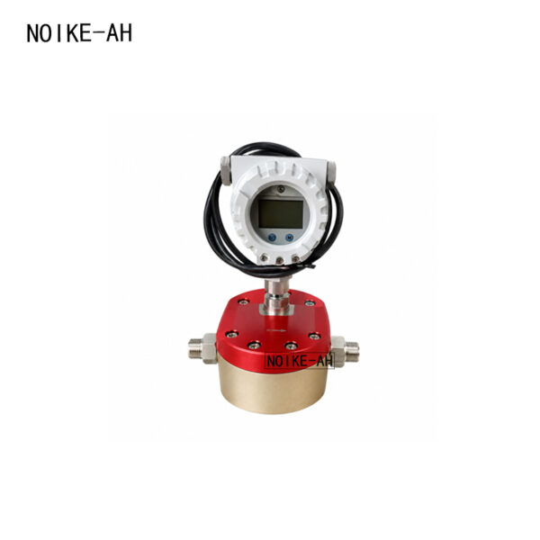
Product Overview
The High Precision Gear Flow Meter is a positive displacement flow meter designed for accurate measurement of high-viscosity liquids and demanding industrial process applications. Engineered for stable performance under high pressure, extreme temperatures, and corrosive media, it provides reliable flow measurement for a wide variety of industrial fluids.
The flow meter supports both pulse output and analog output, making it suitable for integration with PLC, DCS, SCADA, and industrial control systems. With a wide turndown ratio of 1:100, high measurement repeatability, and strong resistance to contamination and corrosion, it is suitable for continuous flow monitoring, batching, dosing, and quantitative control.
Product Features
- High pressure resistance: 1.0–45 MPa
- Wide operating temperature range: -196°C to 200°C
- Suitable for various viscous liquids
- High measurement accuracy and repeatability
- Pulse output available
- Analog output available
- Wide turndown ratio: 1:100
- Broad measurement range
- Strong corrosion resistance
- Resistant to acidic and alkaline media
- Suitable for quantitative fluid control systems
Applications
Suitable Media
- Resin
- Glue
- Hydraulic oil
- Lubricating oil
- Grease
- Fuel oil
- Printing ink
- Asphalt
- Liquid nitrogen
- Refrigerant
- Solvents
- Edible oil
- Fish oil
- Canning liquids
- Chemical fluids
- Corrosive liquids
Typical Applications
- Viscous liquid flow measurement
- Chemical process flow monitoring
- Food processing
- Fuel measurement
- Hydraulic systems
- Lubrication systems
- Batch dosing
- Fluid quantitative control systems
Technical Highlights
| Feature | Specification |
|---|---|
| Pressure Resistance | 1.0–45 MPa |
| Temperature Range | -196°C to 200°C |
| Turndown Ratio | 1:100 |
| Output Options | Pulse Output / Analog Output |
| Media Compatibility | High-viscosity and corrosive liquids |
| Measurement Capability | High accuracy and repeatability |
Output Options
The gear flow meter supports multiple industrial signal outputs:
- Pulse Output
- Analog Output
These outputs enable integration with industrial automation systems, monitoring equipment, and quantitative control applications.
Why Choose This Gear Flow Meter?
Industrial processes involving viscous or corrosive liquids require accurate and repeatable flow measurement under challenging operating conditions. This gear flow meter combines broad media compatibility with stable measurement performance for demanding industrial applications.
Designed for High-Viscosity Liquids
The meter is suitable for measuring a wide range of viscous fluids, including oils, resins, adhesives, grease, ink, and asphalt.
Wide Operating Conditions
Designed to operate under pressures from 1.0 MPa to 45 MPa and temperatures from -196°C to 200°C, the meter adapts to various industrial environments.
Flexible Signal Outputs
Both pulse and analog outputs are available, allowing connection to PLCs, DCS, SCADA systems, and process controllers.
High Measurement Stability
High measurement accuracy and repeatability help maintain consistent flow monitoring and quantitative process control.
Corrosion Resistance
The meter is suitable for chemical fluids and media requiring corrosion resistance, including acidic and alkaline liquids.
Application Case
High-Viscosity Fluid Measurement in Chemical Production
In chemical manufacturing, accurate measurement of high-viscosity media such as resin, adhesives, lubricants, and chemical liquids is essential for maintaining product quality and process consistency. The high precision gear flow meter can be installed in process pipelines or dosing systems to continuously monitor fluid flow.
The meter provides pulse or analog output signals for transmission to PLC or process control systems, supporting real-time monitoring and quantitative control. Its wide turndown ratio enables stable measurement across varying flow conditions, while its resistance to high pressure, extreme temperatures, and corrosive media makes it suitable for continuous operation in demanding industrial environments.
Frequently Asked Questions (FAQ)
1. What types of media can this gear flow meter measure?
It is suitable for a wide range of media, including:
- Resin
- Glue
- Hydraulic oil
- Lubricating oil
- Grease
- Fuel oil
- Printing ink
- Asphalt
- Liquid nitrogen
- Refrigerant
- Solvents
- Edible oil
- Fish oil
- Chemical fluids
- Corrosive liquids
2. What is the operating pressure range?
The pressure resistance is 1.0–45 MPa.
3. What is the operating temperature range?
The flow meter operates from -196°C to 200°C.
4. What output signals are available?
The meter supports:
- Pulse Output
- Analog Output
5. What is the turndown ratio?
The turndown ratio is 1:100.
6. Is the flow meter suitable for corrosive media?
Yes. It is designed for fluids requiring corrosion resistance, including acidic and alkaline media.
7. Can it measure high-viscosity liquids?
Yes. The meter is specifically designed for measuring various viscous liquids.
8. What applications is it suitable for?
Typical applications include chemical processing, lubrication systems, hydraulic systems, food processing, fuel measurement, and quantitative fluid control systems.
Optional Services
- Pulse or analog output configuration
- Customized specifications based on application requirements
- Technical support
- Installation and commissioning assistance
- Fluid measurement solution consultation
Industries Served
The gear flow meter is suitable for a wide range of industries, including:
-
- Chemical Processing
- Petrochemical
- Oil & Gas
- Machinery Manufacturing
- Hydraulic Systems
- Lubrication Systems
- Food Processing
- Pharmaceutical Manufacturing
- Environmental Protection
- Industrial Automation
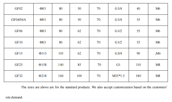
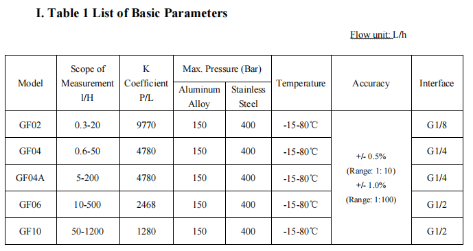
Performance Parameters
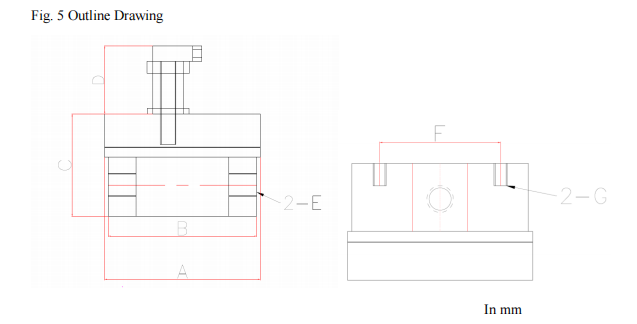


Installation Requirements
- The transmitter should be installed in a position that facilitates maintenance and repairing instead of an
environment with high temperature, strong mechanical vibration and strong magnetic field interference and
corrosion.
- The transmitter should be generally installed on the assembly horizontally and firmly with screw. The liquid
direction must be upward once it is installed vertically. The liquid should be filled in the pipeline and bubbles
must be avoided.
- A straight pipe section which is 20 times of the nominal diameter should be set or rectifier should be installed at 9 / 9
the upstream of transmitter while a straight pipe section which is 5 times of the nominal diameter should be set
at the downstream.
- When the transmitter accessories are installed, the base central line should point to the pipe central line and the
gasket at the connected part cannot be inside the liquid.
- Flow regulating valve must be installed at the downstream of the transmitter, if any.
- When transmitter is installed on a new pipe, a filter is suggested to be installed in the upstream of the transmitterto prevent the sundries inside the pipe from entering the transmitter.
- Bypass pipe should be installed near the installation site of the transmitter in order to avoid normal liquidtransmission in course of overhaul.
- The magnetic field near gear flow transmitter and similar interference source may affect the transmitter from collecting signal. The transmitter and display instrument should be connected via the shield cable with metal. Theshielding layer of transmission cable should be earthed at the display instrument site.