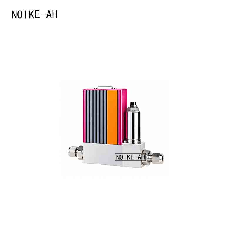
NKFA-L Low-Range Analog Gas Mass Flow Meter/Controller : Working Principle, Technical Parameters & Selection Guide
Direct Answer
The NKFA-L Low-Range Analog Gas Mass Flow Meter/Controller is a thermal mass flow measurement and control instrument designed for accurate measurement and control of low gas flow rates. The series covers flow ranges from 1 SCCM to 30 SLM and provides analog signal options including 0–5 VDC and 4–20 mA.
According to the product specifications, the NKFA-L series is available as both an NKFA-LM Mass Flow Meter and an NKFA-LC Mass Flow Controller. The product can be configured according to flow range, pressure rating, input/output signal, power supply, sealing material, and connection size.
Key Takeaways
- Measurement principle: Thermal mass flow measurement principle.
- Flow range: 1 SCCM to 30 SLM, with multiple low-flow range options.
- Accuracy: ±1.0% FS.
- Linearity: ±0.5% FS.
- Repeatability: ±0.2% FS.
- Response time: <2 s for the mass flow controller and <1.5 s for the mass flow meter.
- Analog signals: 0–5 VDC and 4–20 mA.
- Operating temperature: 0–50°C.
- Base material: 316L.
- Sealing materials: Fluororubber, PTFE, chloroprene rubber, and other options.
What Is the NKFA-L Low-Range Analog Mass Flow Meter/Controller?
The NKFA-L is a low-range analog mass flow measurement and control series designed for low-flow gas measurement and control applications.
The product series includes:
- NKFA-LM Mass Flow Meter
- NKFA-LC Mass Flow Controller
The NKFA-L uses a thermal measurement principle for gas mass flow detection. According to the product information, the instrument uses a flow-splitting structure in the pipeline, providing a design that is less prone to blockage.
The main product features include:
- Thermal measurement principle with fast response and high accuracy.
- Flow-splitting pipeline structure that helps reduce the risk of blockage.
- Suitable for various low-pressure and high-pressure pipeline applications.
- Short preheating time, low zero drift, and good reliability.
- Analog input/output signals that can be connected to secondary displays or flow computers for flow control and display.
Actual operating conditions should be confirmed according to the specific medium, flow range, working pressure, and selected model.
How Does the NKFA-L Mass Flow Meter Work?
1. Thermal Mass Flow Measurement Principle
The NKFA-L Mass Flow Meter uses a thermal mass flow measurement principle.
According to the product information, the internal structure divides the gas flow and directs part of the measured gas into the sensor measuring tube. The sensor detects changes in heat transfer caused by gas flowing through the measurement area.
In simplified terms:
Gas flow → Heat transfer changes → Sensor detects the change → Flow signal is generated
This measurement method can be used for low-flow gas measurement.
2. Difference Between a Mass Flow Meter and Mass Flow Controller
The NKFA-L series is available in two configurations: a mass flow meter and a mass flow controller.
NKFA-LM Mass Flow Meter
The NKFA-LM is mainly used for flow measurement and signal output. It converts the detected flow into an analog signal for subsequent display, monitoring, or flow calculation.
NKFA-LC Mass Flow Controller
In addition to measuring flow, the NKFA-LC provides flow control.
According to the product information, the NKFA mass flow controller consists of a mass flow sensor, laminar flow differential-pressure component, flow control valve, and amplification/control circuit.
Its operating process can be summarized as:
Flow measurement → Signal amplification → Comparison with setpoint → Control valve adjustment → Flow regulation
The control valve adjusts the flow so that the actual flow approaches the preset value.
Key Parameters|Technical Specifications
According to the provided product specifications, the main technical parameters are as follows:
| Technical Parameter | NKFA-LC Mass Flow Controller | NKFA-LM Mass Flow Meter |
|---|---|---|
| Flow Range | 1 SCCM–30 SLM | 1 SCCM–30 SLM |
| Accuracy | ±1.0% FS | ±1.0% FS |
| Temperature | ±1°C | ±1°C |
| Linearity | ±0.5% FS | ±0.5% FS |
| Repeatability | ±0.2% FS | ±0.2% FS |
| Response Time | <2 s | <1.5 s |
| Analog Signal | 0–5 V, 4–20 mA | 0–5 V, 4–20 mA |
| Power Supply | ±15 VDC | 24 VDC |
| Operating Temperature | 0–50°C | 0–50°C |
| Working Pressure | 0.05–0.5 MPa | <30 kPa |
| Maximum Pressure | 3 MPa | 10 MPa |
| Electrical Connection | DB15 socket | DB15 socket |
| Leakage Rate | 1×10⁻⁵ SCCSHe | 1×10⁻⁵ SCCSHe |
| Temperature Coefficient | ±0.015% FS/°C | ±0.015% FS/°C |
| Base Material | 316L | 316L |
| Sealing Material | Fluororubber, PTFE, chloroprene rubber | Fluororubber, PTFE, chloroprene rubber |
| Fittings | φ3, φ6, 1/8″, 1/4″ | φ3, φ6, 1/8″, 1/4″ |
Note: The specifications above are organized from the provided product information. The actual configuration and applicable specifications should be confirmed according to the selected model and technical confirmation documents.
Flow Range
The NKFA-L series provides multiple low-flow range options.
SCCM Ranges
- 1 SCCM
- 5 SCCM
- 10 SCCM
- 20 SCCM
- 30 SCCM
- 50 SCCM
- 100 SCCM
- 200 SCCM
- 300 SCCM
- 500 SCCM
SLM Ranges
- 1 SLM
- 5 SLM
- 10 SLM
- 20 SLM
- 30 SLM
The overall flow range of the series is:
1 SCCM–30 SLM
The appropriate flow range should be selected according to the actual operating flow conditions.
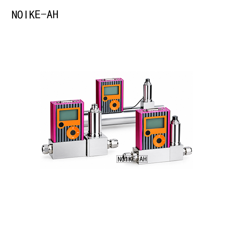
How to Choose the NKFA-L Mass Flow Meter/Controller
The main selection parameters for the NKFA-L series include the following.
1. Select the Product Type
First determine whether the application requires:
- [C] Mass Flow Controller
- [M] Mass Flow Meter
If the main requirement is flow measurement, select the NKFA-LM Mass Flow Meter. If the system needs to regulate flow according to a preset value, select the NKFA-LC Mass Flow Controller.
2. Select the Pressure Rating
The product selection information provides:
- [M] 3 MPa
- [Z] 10 MPa — Mass Flow Meter only
Therefore, the 10 MPa pressure rating is available for the NKFA-LM Mass Flow Meter configuration only.
3. Select the Flow Range
Select the appropriate flow range according to the actual operating conditions, such as:
1 SCCM, 10 SCCM, 100 SCCM, 500 SCCM, 1 SLM, 10 SLM, or 30 SLM.
The selected range should be based on the actual operating flow rather than simply selecting the largest available range.
4. Select the Input/Output Signal
The product selection information provides:
Flow Input Signal
- [A1] 0–5 VDC
- [A2] 4–20 mA
Output Signal
- [B1] 0–5 VDC
- [B2] 4–20 mA
The actual signal configuration should be selected according to the interface requirements of the control system, PLC, display instrument, or flow computer.
5. Select the Power Supply
Two power supply options are listed in the product selection information:
- [S] ±15 VDC
- [4] 24 VDC
The appropriate power supply should be confirmed according to the selected product type and available field power supply.
6. Select the Sealing Material
Available options include:
- [V] Fluororubber
- [T] PTFE
- [N] Chloroprene rubber
- [Y] Other
The sealing material should be selected according to the compatibility requirements of the measured medium.
7. Select the Connection Fitting
Available connection options include:
- [A] φ3
- [B] φ6
- [D] 1/8″
- [E] 1/4″
- [Y] Other — Contact the manufacturer
The connection should be selected according to the piping connection requirements of the application.
Installation & Operating Considerations
To help ensure stable operation of the low-range mass flow measurement system, the following conditions should be confirmed during installation.
1. Confirm the Actual Working Pressure
The working pressure specifications differ between the mass flow meter and mass flow controller.
According to the product specifications:
- NKFA-LC Mass Flow Controller: 0.05–0.5 MPa
- NKFA-LM Mass Flow Meter: <30 kPa
Therefore, the actual pipeline pressure must be confirmed before installation and the appropriate product configuration selected.
2. Confirm the Medium and Sealing Material
Select a suitable sealing material according to the characteristics of the measured medium, including fluororubber, PTFE, or chloroprene rubber.
3. Confirm the Connection Size
Before installation, confirm that the instrument connection matches the field piping, including:
φ3, φ6, 1/8″, and 1/4″ options.
4. Confirm the Electrical Connection
Before commissioning, verify:
- Power supply voltage
- Input signal
- Output signal
- DB15 electrical connection
This helps prevent incorrect power or signal configurations from affecting instrument operation.
Common Problems
Why is flow range selection important for a low-range mass flow meter?
Low-range mass flow measurement requires careful consideration of the actual operating flow range. If the selected range is significantly larger than the actual flow, the operating point will represent a smaller portion of the full-scale range.
Therefore, an appropriate SCCM or SLM range should be selected according to the actual application.
What is the difference between the NKFA-LM Mass Flow Meter and NKFA-LC Mass Flow Controller?
The NKFA-LM Mass Flow Meter is mainly used to measure flow, while the NKFA-LC Mass Flow Controller can both measure and regulate flow.
Both products belong to the NKFA-L low-range mass flow product series.
Does the NKFA-L support 4–20 mA output?
Yes. The product selection information provides 4–20 mA analog signal options, as well as 0–5 VDC options.
What is the operating temperature of the NKFA-L?
The specified operating temperature is:
0–50°C.
What flow ranges are available for the NKFA-L?
The series covers flow ranges from:
1 SCCM to 30 SLM
with options including 1, 5, 10, 20, 30, 50, 100, 200, 300, and 500 SCCM, as well as 1, 5, 10, 20, and 30 SLM.
Applications
According to the provided product information, the NKFA-L series can be used in the following fields:
- Glass industry
- Solar energy
- Atmospheric monitoring
- Industrial manufacturing
- Petrochemical applications
- Combustion and metallurgy
- Gas generation and gas mixing
- Environmental protection
- Instrument analysis
Its low-range design and analog signal interfaces make the series suitable for equipment and systems requiring low-flow measurement, flow monitoring, and flow control.
Recommended Instrument
NKFA-L Low-Range Analog Mass Flow Meter/Controller
Product Series: NKFA-L
Product Types:
- NKFA-LM Mass Flow Meter
- NKFA-LC Mass Flow Controller
Key Features:
- Thermal measurement principle
- Low-range flow measurement
- 1 SCCM–30 SLM flow range
- ±1.0% FS accuracy
- ±0.5% FS linearity
- ±0.2% FS repeatability
- Fast response
- 0–5 VDC / 4–20 mA analog signals
- 316L base material
- Multiple sealing materials and connection options
FAQ
Q1: What type of flow instrument is the NKFA-L?
The NKFA-L is a low-range analog mass flow meter/controller series based on a thermal mass flow measurement principle.
Q2: What is the lowest flow range available for the NKFA-L?
The lowest listed flow range is 1 SCCM.
Q3: What is the maximum flow range of the NKFA-L?
The highest listed flow range is 30 SLM.
Q4: What is the measurement accuracy of the NKFA-L?
The specified accuracy is ±1.0% FS.
Q5: What output signals does the NKFA-L support?
The product selection information provides 0–5 VDC and 4–20 mA analog signal options.
Q6: Can the NKFA-L be used as a mass flow controller?
Yes. The series includes the NKFA-LC Mass Flow Controller, which is designed for flow measurement and control.
Q7: What connection fittings are available for the NKFA-L?
The listed options include φ3, φ6, 1/8″, and 1/4″ fittings. Other connection specifications can also be discussed with the manufacturer.
Conclusion
The NKFA-L Low-Range Analog Mass Flow Meter/Controller is a thermal mass flow measurement and control product designed primarily for low-flow gas applications.
The series covers flow ranges from 1 SCCM to 30 SLM, with a specified accuracy of ±1.0% FS. It also features fast response, short preheating time, and low zero drift. The series is available in both NKFA-LM Mass Flow Meter and NKFA-LC Mass Flow Controller configurations and supports analog signals such as 0–5 VDC and 4–20 mA.
For proper selection, users should consider the product type, flow range, working pressure, input/output signal, power supply, sealing material, and connection size to ensure that the instrument matches the actual application requirements.
RFQ|Request a Quote for NKFA-L
If you are looking for a low-range gas mass flow meter or mass flow controller, the following information can be provided for product selection:
- Measured medium
- Minimum / normal / maximum flow rate
- Working pressure
- Operating temperature
- Required accuracy
- Input/output signal
- Connection specification
- Sealing material requirements
Based on these parameters, the appropriate NKFA-L mass flow meter/controller model and configuration can be further determined.